An electric vehicle battery insulation structure

A technology for electric vehicles and batteries, applied in electric vehicles, structural parts, secondary batteries, etc., can solve the problems of inability to ensure that the liquid and cold water pipes are closely attached, affecting the thermal insulation effect of the thermal insulation structure, and unable to lift the liquid and cold water pipes, etc. Improve the thermal insulation effect, improve the thermal insulation effect, and avoid the effect of bending deformation

Active Publication Date: 2022-06-21
ZHEJIANG LEAPMOTOR TECH CO LTD
View PDF12 Cites 0 Cited by
  • Summary
  • Abstract
  • Description
  • Claims
  • Application Information

AI Technical Summary

Problems solved by technology

[0005] However, the above structure still has the following defects: First, because the insulation cotton material has certain elasticity, that is to say, the insulation cotton can provide elastic support for the liquid-cooled water pipe
Limited by the elasticity of the insulation cotton, when the liquid-cooled water pipe has a certain arc bending deformation, the insulation cotton cannot effectively lift the liquid-cooled water pipe, that is to say, the insulation cotton cannot "straighten" the liquid-cooled water pipe Therefore, it is impossible to ensure that the liquid cooling water pipe is always tightly attached to the battery module
Secondly, although the thermal insulation cotton has a good heat insulation effect, since the thermal insulation cotton and the liquid-cooled water pipe and the bottom wall of the outer shell are fully bonded and contacted at the same time, the thermal insulation cotton will still pass between the liquid-cooled water pipe and the outer shell. Generate a certain amount of heat transfer, thus affecting the overall thermal insulation effect of the thermal insulation structure

Method used


Image

  • An electric vehicle battery insulation structure
  • An electric vehicle battery insulation structure
  • An electric vehicle battery insulation structure

Examples


Embodiment Construction

[0036] The present invention will be further described below with reference to the accompanying drawings and specific embodiments.

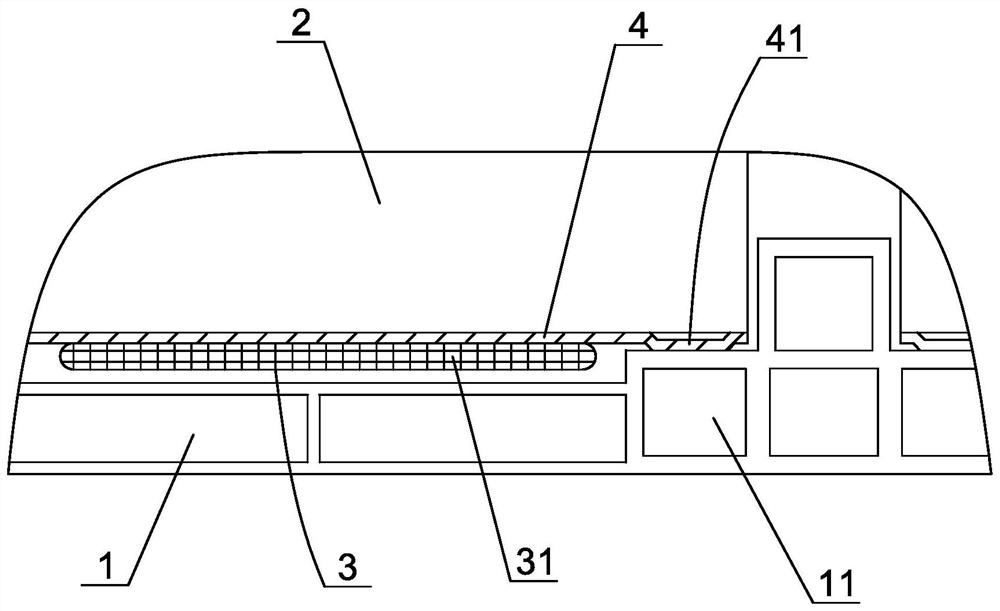
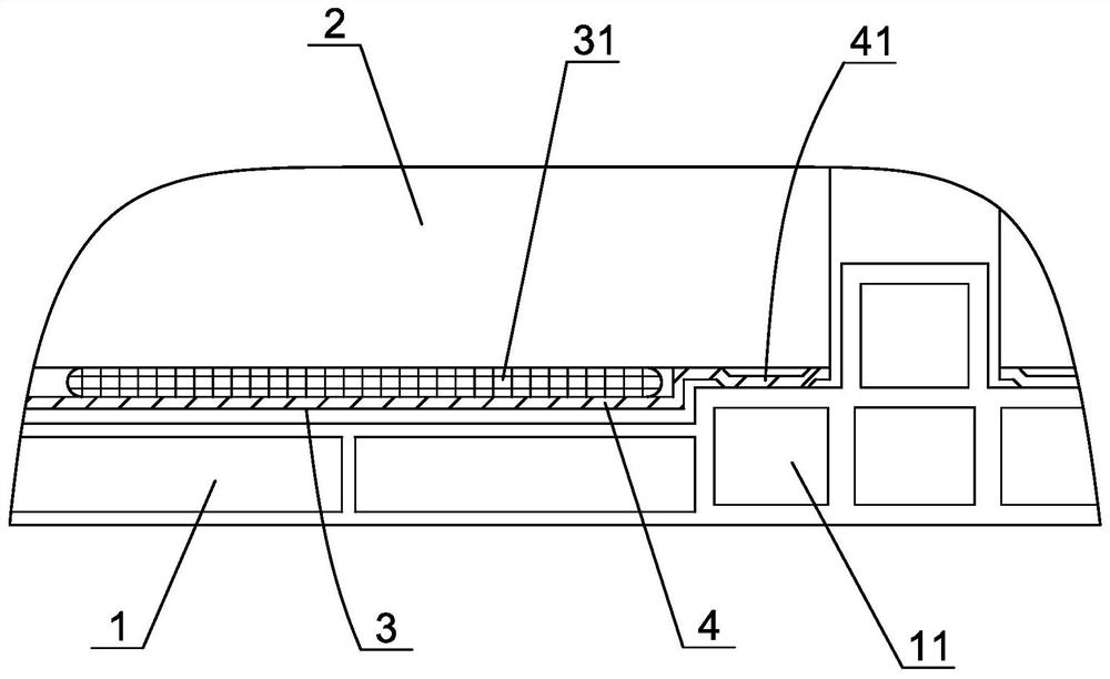
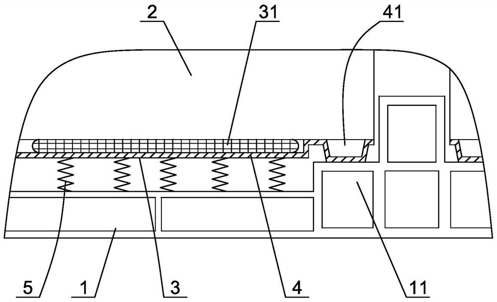
[0037] like figure 1 As shown, an electric vehicle battery insulation structure is mainly used for cooling or heating the lithium ion battery of the electric vehicle, so that the battery can work in a suitable temperature range. Specifically, the battery includes an outer casing 1, a battery module 2 disposed in the outer casing, a supporting beam 11 for supporting the battery module is arranged on the bottom edge of the outer casing, a liquid-cooling water pipe group 3 is arranged on the lower side of the battery module, and the liquid The cold water pipe group includes the liquid cold water pipes 31 arranged side by side and the reinforcing member for improving the bending strength of the liquid cold water pipe. The liquid cold water pipe includes a harmonica pipe in the middle and a collector connected to the front and rear ends of the harmoni...


PUM

PropertyMeasurementUnit
radiusaaaaaaaaaa

Abstract

The invention discloses an electric vehicle battery heat preservation structure. The battery includes an outer casing and a battery module set in the outer casing. A liquid-cooled water pipe group is arranged on the lower side of the battery module. The liquid-cooled water pipe group passes through the water inlet and outlet pipes. The joint is connected to the cooling source, and a support beam for supporting the battery module is provided on the bottom edge of the outer casing, and the liquid-cooled water pipe group includes liquid-cooled water pipes arranged side by side and a reinforcement member for improving the bending strength of the liquid-cooled water pipe, The upper side of the liquid-cooled water tube group is closely attached to the lower side of the battery module, and there is a heat insulation gap between the lower side of the liquid-cooled water tube group and the outer shell, and the strengthening member includes a support protrusion abutting against the support beam. The invention can not only effectively improve the heat insulation effect between the liquid-cooled water pipe and the outer shell, avoid heat conduction between the liquid-cooled water pipe and the outer shell, but also ensure the tight fit between the liquid-cooled water pipe and the battery module , so as to improve the heat preservation effect of the battery.

Description

technical field [0001] The invention belongs to the technical field of electric vehicle manufacturing, and in particular relates to an electric vehicle battery thermal insulation structure. Background technique [0002] For electric vehicles, the lithium-ion battery is a key component. The lithium-ion battery that supplies power to the vehicle usually includes a metal outer casing and a battery module arranged in the outer casing. We know that the lithium-ion battery will generate heat during the charging and discharging process, and the lithium-ion battery is more sensitive to the ambient temperature. The suitable operating temperature of the lithium-ion battery is generally 0 °C ~ 45 °C. If the temperature is too low, the discharge capacity will be reduced. If the temperature is too high, it will cause an internal short circuit in the battery and cause an explosion. For this reason, people usually set a corresponding thermal insulation structure for the lithium-ion batter...

Claims


Application Information

Patent Timeline
Patent Type & Authority Patents(China)
IPC IPC(8): H01M50/204H01M50/249H01M50/256H01M50/24H01M10/658H01M10/6567B60L58/24
CPCH01M10/658H01M10/6567B60L58/24Y02T10/70
Inventor 田永杰
Owner ZHEJIANG LEAPMOTOR TECH CO LTD
Why Eureka
Try Eureka