Eureka AIR delivers breakthrough ideas for toughest innovation challenges, trusted by R&D personnel around the world.

Boring clamp for machining gear milling machine special-shaped oil cylinder and machining method

A gear milling machine and oil cylinder technology, which is applied to metal processing machinery parts, manufacturing tools, metal processing equipment, etc., can solve the problems of increasing the manufacturing cost of special-shaped oil cylinders, unstable quality, and low processing efficiency, so as to save energy and operate Simple and time-saving effect

Inactive Publication Date: 2014-01-22
TIANJIN NO 1 MACHINE TOOL WORKS
View PDF5 Cites 4 Cited by
  • Summary
  • Abstract
  • Description
  • Claims
  • Application Information

AI Technical Summary

Problems solved by technology

The above method needs to be processed one by one, and the operation is cumbersome, the processing efficiency is low, the quality is unstable, scrapped parts often occur, and the manufacturing cost of special-shaped cylinders is increased.

Method used


Image

  • Boring clamp for machining gear milling machine special-shaped oil cylinder and machining method
  • Boring clamp for machining gear milling machine special-shaped oil cylinder and machining method
  • Boring clamp for machining gear milling machine special-shaped oil cylinder and machining method

Examples


Embodiment Construction

[0031] In order to further understand the invention content, characteristics and effects of the present invention, the following examples are given, and detailed descriptions are as follows in conjunction with the accompanying drawings:

[0032] It should be noted that, unless otherwise specified and limited, terms such as "first" and "second" do not represent sequential installation, nor do they represent the importance of the described components.

[0033] Examples of the described embodiments are shown in the drawings, wherein like or similar reference numerals designate like or similar elements or elements having the same or similar functions throughout.

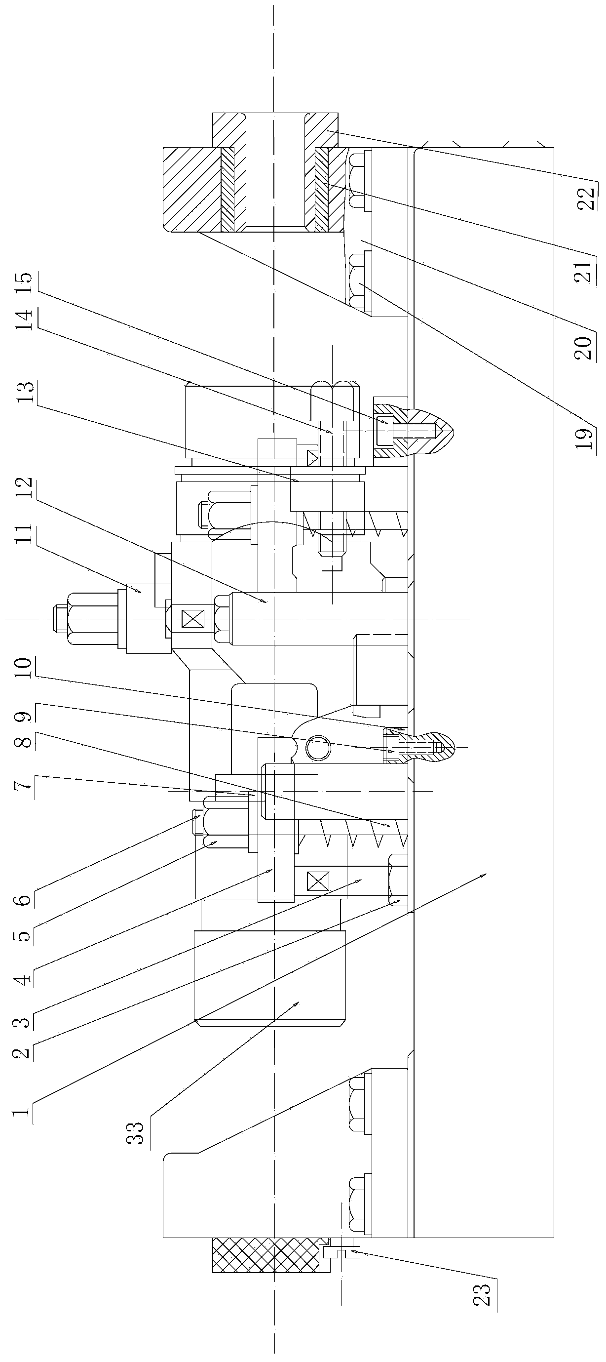
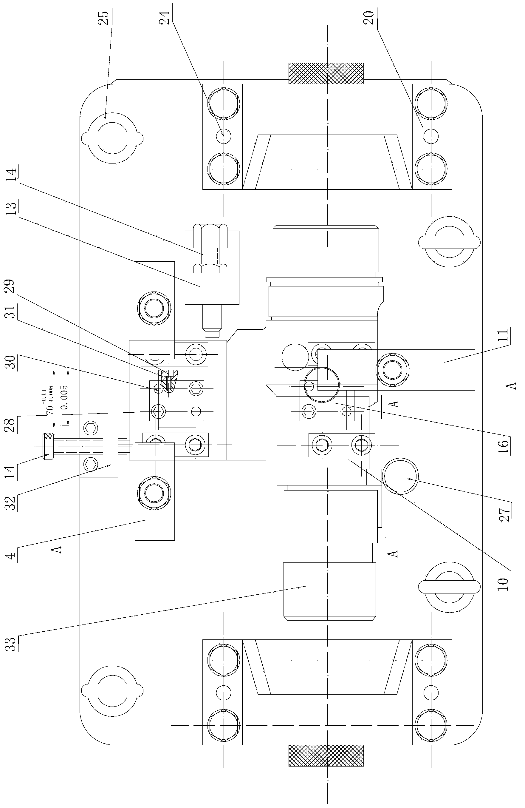
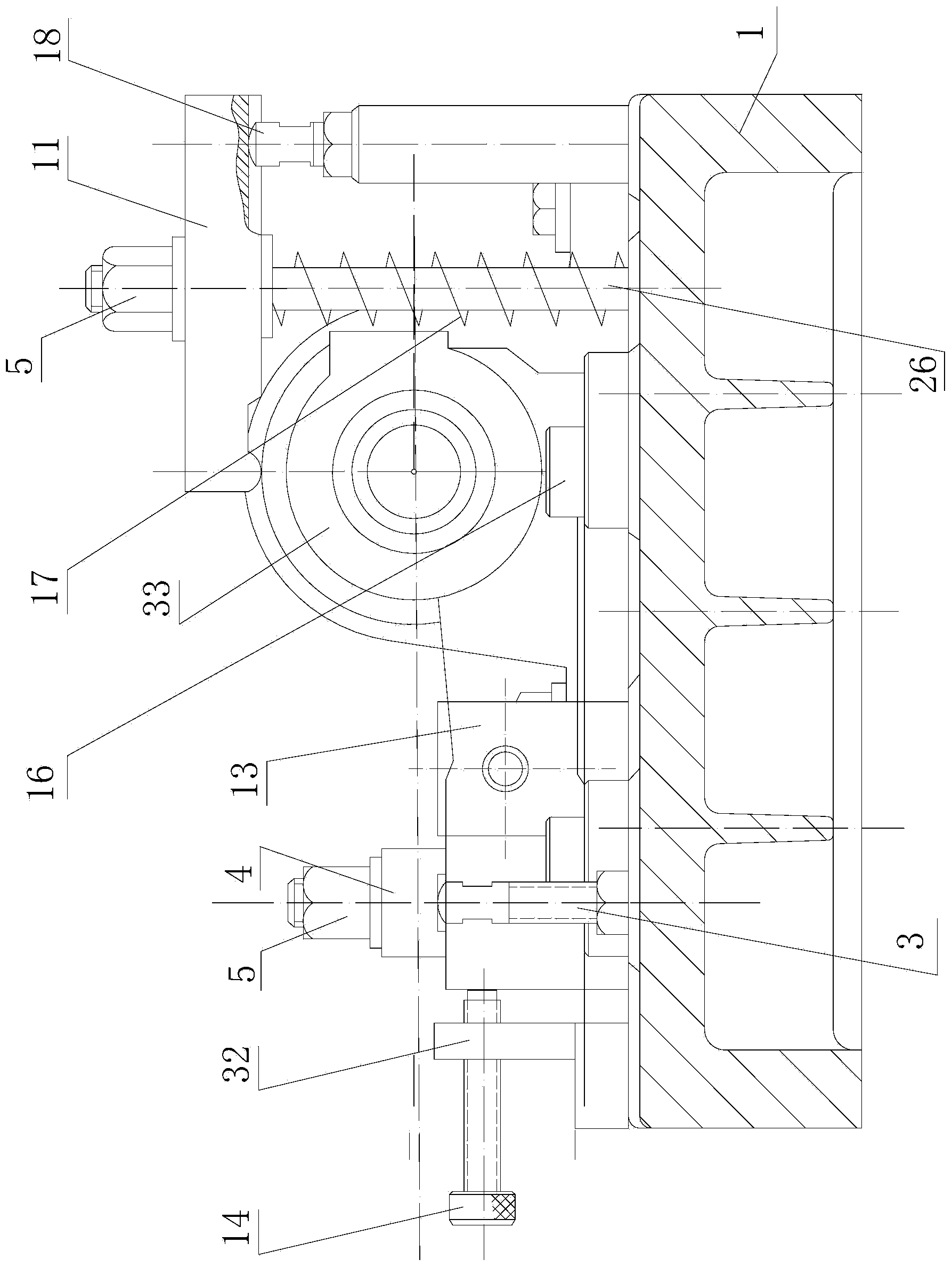
[0034] see Figure 1-Figure 6 , the boring fixture for processing the special-shaped oil cylinder of the gear milling machine, including the fixture base 1, and the center position of the fixture base is provided with two sets of supporting plates 10 corresponding to each other for controlling the distance from the botto...


PUM


Abstract

The invention relates to a boring clamp for machining a gear milling machine special-shaped oil cylinder and a machining method. The boring clamp is characterized in that the boring clamp comprises a clamp base, supporting plates arranged on the clamp base and a locating frame arranged between each set of supporting plates, wherein locating supporting plates matched with rectangular grooves in the bottom of the special-shaped oil cylinder are mounted on the locating frames; the boring clamp comprises a first screw frame and a second screw frame which are mounted on the upper end face of the clamp base, the first screw frame corresponds to one side face of the rectangular body of the special-shaped oil cylinder, the second screw frame corresponds to the other side face of the rectangular body of the special-shaped oil cylinder, and the first screw frame and the second screw frame are provided with first adjusting screws and boring rod supports, wherein the boring rod supports are symmetrically arranged on the two sides of the upper end face of the clamp base; the boring clamp further comprises locating pins, a pressing plate used for pressing the periphery of the special-shaped oil cylinder and a rectangular body upper end face pressing plate. The boring clamp has the advantages that machining precision and production efficiency of holes of the special-shaped oil cylinder can be greatly improved, and operation is simple, aligning only needs to be conducted at one time when the boring clamp is used for machining a batch of workpieces, and the boring clamp is especially suitable for production of batches of special-shaped oil cylinders; the special-shaped oil cylinder can be prevented from being deformed in the hole machining process, and geometric dimensioning precision of the machined special-shaped oil cylinder can be guaranteed.

Description

technical field [0001] The invention belongs to the technical field of mechanical equipment, and in particular relates to a boring fixture and a processing method for processing special-shaped oil cylinders of gear milling machines. Background technique [0002] The special-shaped oil cylinder is the key part of the internal chain transmission in the spiral bevel gear milling machine tool, and there are such parts in the gear milling machine series. Special-shaped oil cylinder drawing requirements: 1. The total length of the special-shaped oil cylinder is 450mm. In the middle of the oil cylinder, there is a rectangular body perpendicular to the outer circle and inner hole. The size is 225mm×140mm×57mm. For cylinders Φ90g5 and Φ130g5 on both sides of the groove, please refer to Figure 4 and Figure 5 . 1. The verticality of the center line of the special-shaped cylinder to the rectangular groove is within 100mm, and the verticality of the groove to the bottom surface C is ...

Claims


Application Information

Patent Timeline
Patent Type & Authority Applications(China)
IPC IPC(8): B23Q3/06B23B35/00
CPCB23B35/00B23B47/00B23Q3/062
Inventor 吴金栋齐子有高培琴徐思李彪
Owner TIANJIN NO 1 MACHINE TOOL WORKS
Why Eureka
Eureka Blog
Learn More