Tool special for controlling peeling of cable

A special tool and cable control technology, which is applied in the direction of dismantling/armoring cable equipment, etc., can solve problems such as cable knife slippage or uneven depth control, failure to meet safety production, cable core insulation damage, etc.

Active Publication Date: 2014-01-15
STATE GRID CORP OF CHINA +1
View PDF5 Cites 18 Cited by
  • Summary
  • Abstract
  • Description
  • Claims
  • Application Information

AI Technical Summary

Problems solved by technology

[0005] The existing method mainly relies on manual control of the moving speed and depth of the cable cutter head. The cable is a cylindrical structure with a relatively smooth surface. When the cable cutter is manually controlled, the cable cutter often slips or the depth control is uneven, causing personnel Injury or cable core insulation damage, this method has a lot to do with the technical level of the operator, even skilled personnel are difficult to avoid accidents
This method is not only inefficient, but also highly dangerous. It can no longer meet the requirements of safe production, and the quality of the finished construction products does not meet the requirements of construction and acceptance specifications and standard processes. Improvement is urgently needed.

Method used


Image

  • Tool special for controlling peeling of cable
  • Tool special for controlling peeling of cable
  • Tool special for controlling peeling of cable

Examples


Embodiment 1

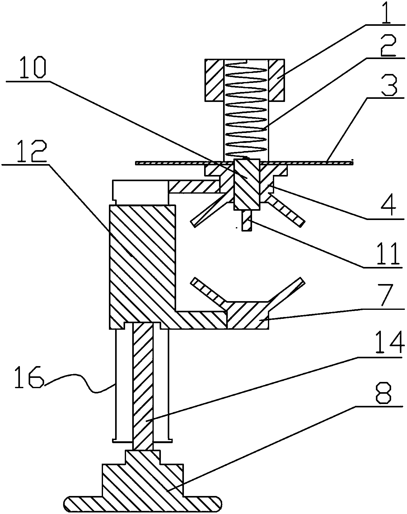
[0022] Embodiment 1: as figure 1 , figure 2 , Figure 5 , Figure 6 , Figure 7 , Figure 8 , Figure 9 As shown, the present invention includes a sleeve 13, and a first sliding groove 16 is provided on the side wall of the sleeve 13, and a movable slider structure is arranged in the first sliding groove 16, and the movable slider structure includes a second slider 12. Screw 14, the end of the second slider 12 is provided with an adjusting screw mounting hole, the head of the adjusting screw 14 is rotationally connected with the adjusting screw mounting hole, and the bottom of the sleeve 13 is provided with a threaded hole corresponding to the adjusting screw 14 , the adjusting screw 14 passes through the threaded hole at the bottom of the sleeve 13 , and the tail of the adjusting screw 14 is provided with an adjusting knob 8 . The second slider 12 is fixedly provided with a mobile cable clamp 7, and a corresponding fixed cable clamp 4 is arranged above the mobile cable...

Embodiment 2

[0023] Embodiment 2: as image 3 , Figure 4 , Figure 5 , Figure 6 , Figure 7 , Figure 8 , Figure 9As shown, the present invention includes a sleeve 13, and a first sliding groove 16 is provided on the side wall of the sleeve 13, and a movable slider structure is arranged in the first sliding groove 16, and the movable slider structure includes a second slider 12. A second spring 15 is arranged on the second slider 12 , one end of the second spring 15 is fixedly connected to the second slider 12 , and the other end of the second spring 15 is fixedly connected to the bottom of the sleeve 13 . The second slider 12 is fixedly provided with a mobile cable clamp 7, and a corresponding fixed cable clamp 4 is arranged above the mobile cable clamp 7. The fixed cable clamp 4 is fixedly connected with the upper end of the sleeve 13, and the fixed cable clamp 4 The upper side is provided with a hollow screw 9, one end of the hollow screw 9 is fixedly connected with the fixed c...


PUM


Abstract

The invention discloses a tool special for controlling peeling of a cable. The tool comprises a sleeve, the side wall of the sleeve is provided with a first sliding groove, the inside of the first sliding groove is provided with a movable sliding block structure, the movable sliding block structure is fixedly provided with a movable cable clamp, the upper portion of the movable cable clamp is provided with a corresponding fixed cable clamp, the face, opposite to the movable cable clamp, of the fixed cable clamp is fixedly provided with a sliding bearing, a ball-shaped universal wheel is arranged in a bearing bush of the sliding bearing, and one portion of a ball-shaped wheel of the ball-shaped universal wheel is located outside the sliding bearing. The tool can be used for peeling outer skin of control cables of various models, work efficiency of the cutting process is more than twice than that of a traditional method, cable wire cores and safety of operators can be effectively protected, and good practical value is achieved.

Description

technical field [0001] The invention belongs to the field of control cable construction of a power system substation (converter station), and in particular relates to a special tool for stripping control cables. Background technique [0002] In the composition of the substation, there are primary equipment and secondary equipment. The secondary equipment plays a role in monitoring, protecting and controlling the primary equipment. The realization of these functions requires the transmission of electrical signals through control cables. Therefore, the control cables in the substation Construction is an important part. In conventional substation (converter) station construction, the cable construction process is as follows: the cable is laid in place → the outer insulation is stripped off at both ends according to the reserved length → the steel armor is stripped off → the inner insulation layer is stripped off → the shielding layer is stripped off → Wire core processing → wi...

Claims


Application Information

Patent Timeline
Patent Type & Authority Applications(China)
IPC IPC(8): H02G1/12
Inventor 陈东升张斌刘军刘金柱周亚辉张新旺苗国立
Owner STATE GRID CORP OF CHINA
Why Eureka
Try Eureka