Plasma etching device
An etching device and plasma technology, applied in discharge tubes, electrical components, circuits, etc., can solve problems such as uneven etching of wafers, and achieve the effects of weakening coherence, uniform electric field distribution, and high etching uniformity
- Summary
- Abstract
- Description
- Claims
- Application Information
AI Technical Summary
Problems solved by technology
Method used
Image
Examples
no. 1 example
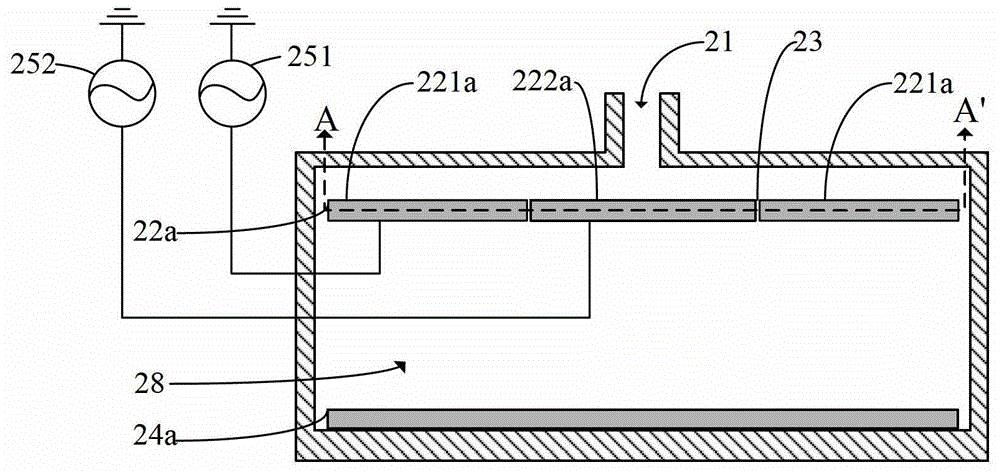
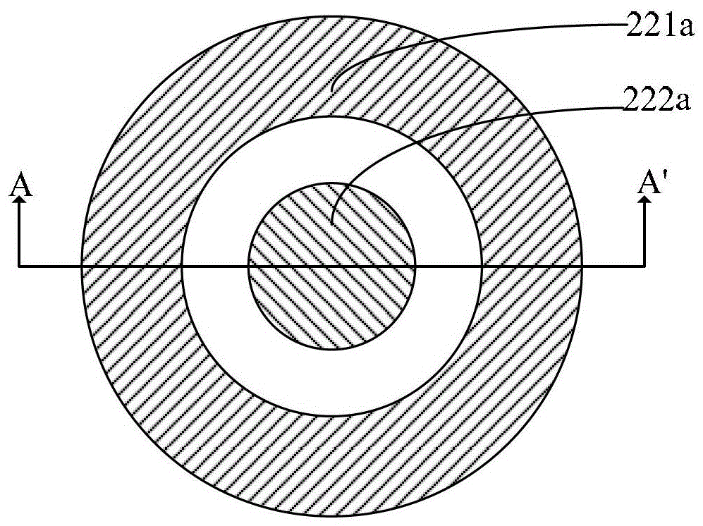
[0044] refer to figure 2 , in the first embodiment, the plasma etching device includes: a process chamber 28 having an opening 21; a first electrode 22a and a second electrode 24a located in the process chamber 28, and the first electrode is opposite to the second electrode Placement, the first electrode is positioned at the top of the process chamber, wherein the first electrode 22a includes a pole plate 221a and a pole plate 222a; an excitation radio frequency unit, the number of excitation radio frequency units is equal to the number of pole plates, and each pole plate is connected to each pole plate The excitation radio frequency units are electrically connected one to one, and the excitation radio frequency units are used to provide excitation energy to the etching gas in the process chamber through each plate of the first electrode. In this first embodiment, two excitation radio frequency units are included , are respectively the excitation radio frequency unit 251 elec...
no. 2 example
[0055] refer to Image 6 , in the second embodiment, the plasma etching device includes: a low-frequency capacitively coupled RF generator 261 and a DC power supply 262 electrically connected to the second electrode 24b, and the other end of the low-frequency capacitively coupled RF generator 261 and the DC power supply 262 grounded. Among them, the low-frequency capacitively coupled RF generator 261 forms a low-frequency oscillating electric field in the process chamber 28 by providing a bias voltage to the second electrode 24b; form a stable electric field. The low-frequency oscillating electric field and stable electric field propagating in the process chamber 28 can change the movement direction of electrons in the plasma in the process chamber 28, thereby changing the propagation direction of part of the electromagnetic waves generated by the high-speed movement of electrons in the process chamber 28, This can further reduce or even eliminate standing wave effects. The...
no. 3 example
[0059] refer to Figure 7 , in the third embodiment, the second electrode 24c includes two pole plates, namely pole plate 241c and pole plate 242c, wherein, pole plate 241c is electrically connected with one end of the low-frequency capacitive coupling RF generator 261, and the low-frequency capacitive coupling The other end of the RF generator 261 is grounded; one end of the plate 242c is electrically connected to the DC power supply 262, and the other end of the DC power supply 262 is grounded.
[0060] In the third embodiment, the shape and positional relationship of the two plates included in the second electrode 24c are the same as those of the two plates of the first electrode in the first embodiment, and will not be described in detail here. In addition, the number of pole plates of the second electrode is not limited to two pole plates, and may be three or more including three. The number of pole plates of the first electrode is the same as the number of pole plates o...
PUM
 Abstract
Description
Claims
Application Information
 - R&D
- Intellectual Property
- Life Sciences
- Materials
- Tech Scout
- Unparalleled Data Quality
- Higher Quality Content
- 60% Fewer Hallucinations
Browse by: Latest US Patents, China's latest patents, Technical Efficacy Thesaurus, Application Domain, Technology Topic, Popular Technical Reports.
© 2025 PatSnap. All rights reserved.Legal|Privacy policy|Modern Slavery Act Transparency Statement|Sitemap|About US| Contact US: help@patsnap.com


