Eureka AIR delivers breakthrough ideas for toughest innovation challenges, trusted by R&D personnel around the world.

Drain valve

A technology of drain valve and water valve, applied in valve details, valve device, valve operation/release device, etc., can solve problems such as leakage, poor piston sealing, slow recovery speed of water valve piston, etc., to avoid leakage, The piston closes tightly and avoids the effect of reversal

Active Publication Date: 2014-01-15
JIANGSU LEILI MOTOR
View PDF7 Cites 8 Cited by
  • Summary
  • Abstract
  • Description
  • Claims
  • Application Information

AI Technical Summary

Problems solved by technology

Because the opening and closing of the water valve piston is driven by the rotation of the motor, the recovery speed of the water valve piston is relatively slow, which may cause the piston to not seal tightly and cause leakage

Method used


Image

  • Drain valve
  • Drain valve
  • Drain valve

Examples


Embodiment 1)

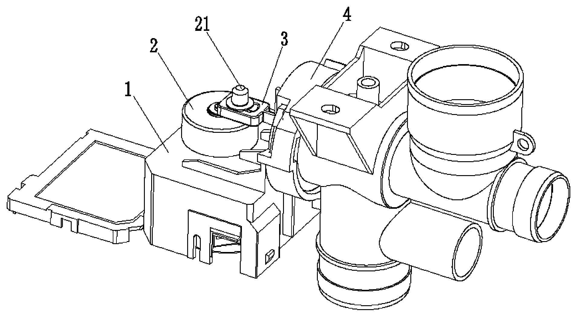
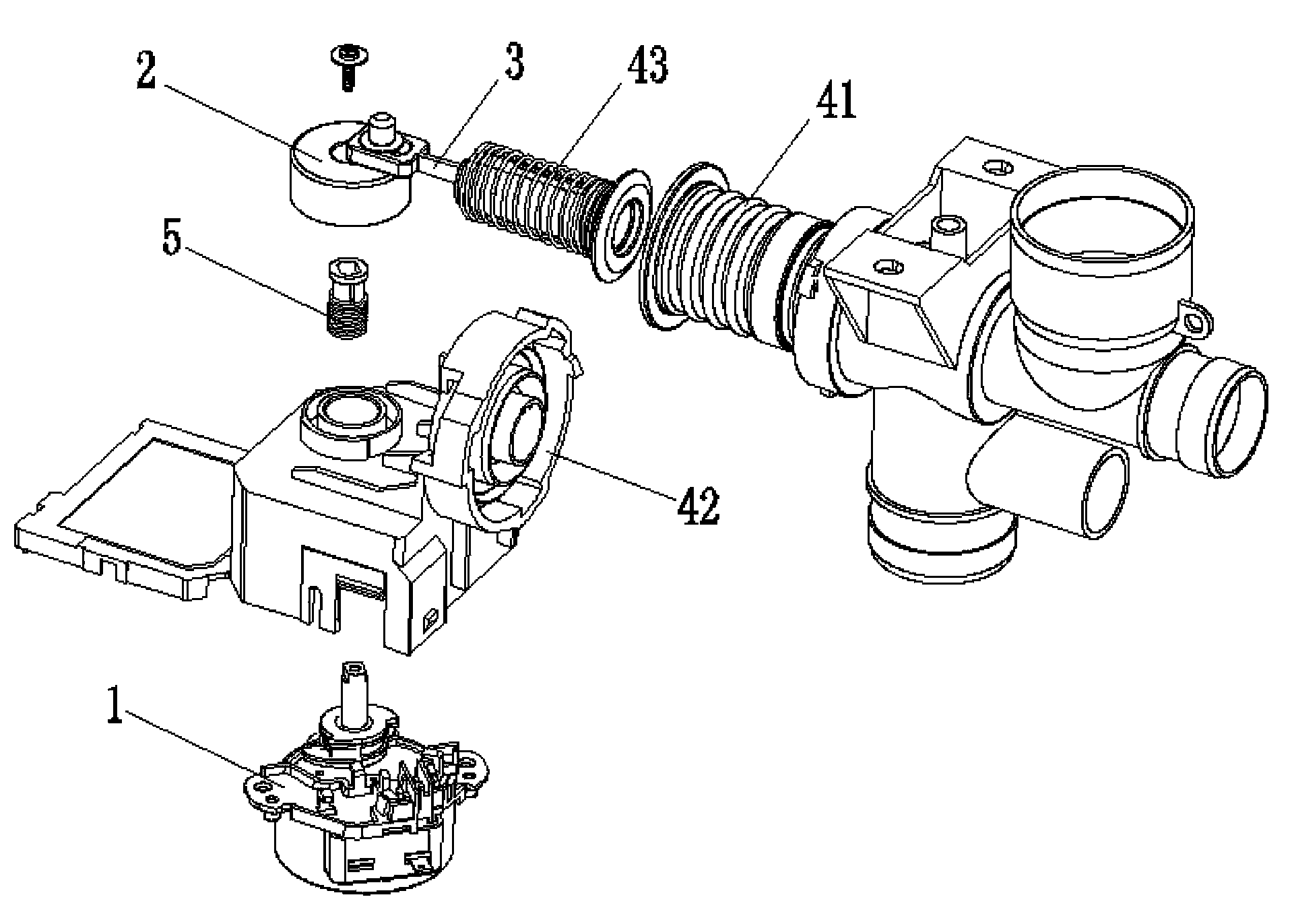
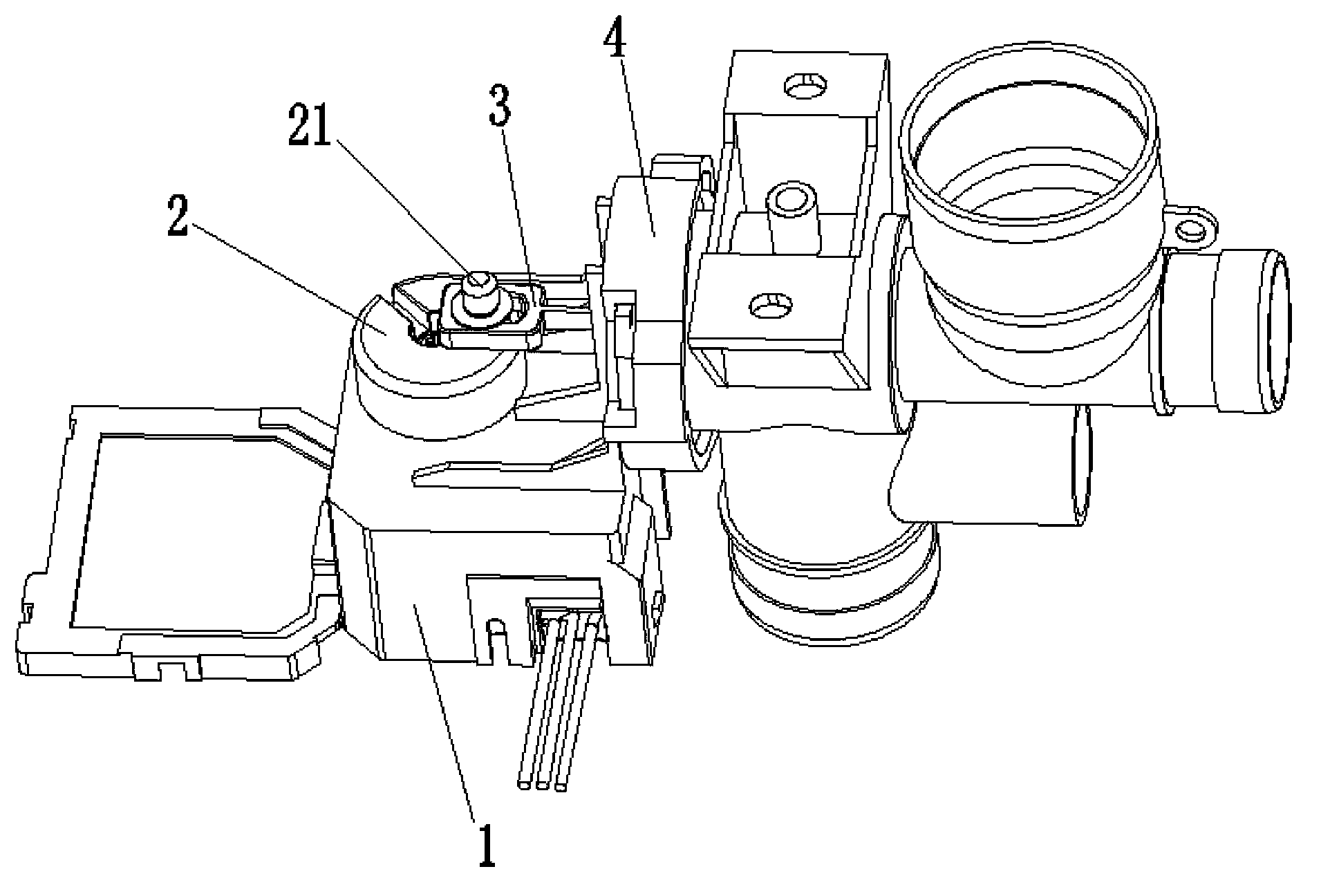
[0026] See figure 1 and figure 2 , The drain valve of this embodiment includes a motor 1, a cam 2, a connecting rod 3, a water valve 4 and an acceleration mechanism.

[0027] The cam 2 is installed on the output shaft of the motor 1, and the cam 2 is provided with a connecting rod shaft 21. One end of connecting rod 3 is installed on the connecting rod shaft 21, and the other end is installed on the piston 41 of water valve 4. A spring 43 sleeved on the connecting rod 3 is provided between the piston 41 of the water valve 4 and the end cover 42 . The acceleration mechanism is arranged in the motor 1, and can accelerate the speed at which the cam 2 pushes the piston 41 of the water valve 4 to close.

[0028] The acceleration mechanism includes a torsion spring 5 . The torsion spring 5 is sleeved on the output shaft of the motor 1 , and the outer wall of the torsion spring 5 is in close contact with the inner wall of the cam 2 .

[0029] The motor 1 rotates, drives the tor...

Embodiment 2)

[0031] See Figure 3 to Figure 7 , the present embodiment is basically the same as Embodiment 1, the difference is that the acceleration mechanism includes a slide bar 6, and coaxially arranged two wheel pieces 7 and two wheel shaft teeth 8 that can be separated and engaged, and are arranged on the output of the motor 1 Track groove 9 on the axle gear, and the stage clip that is arranged between two wheel pieces 7 and two axle teeth 8.

[0032] Cam 2 is fixed on the output shaft of motor 1. The slide bar 6 can rotate around the center, one end of the slide bar 6 is slidably connected with the track groove 8, and the other end controls the separation and engagement of the second wheel piece 7 and the second wheel axle tooth 8. The outer teeth of the two wheel blades 7 mesh with the rotor assembly of the motor 1 . The outer teeth of the two axle teeth 8 mesh with the first stage gear of the reduction gear set of the motor 1 .

[0033] See Figure 8 , The lower end surface of...


PUM


Abstract

The invention discloses a drain valve which comprises a motor, a cam, a connecting rod and a water valve. The cam is arranged on an output shaft of the motor, and a connecting rod shaft is arranged on the cam; one end of the connecting rod is arranged on the connecting rod shaft, and the other end of the connecting shaft is arranged on a piston of the water valve; a spring arranged on the connecting rod in a sleeved mode is arranged between the piston of the water valve and an end cover; the drain valve further comprises an accelerating mechanism which is arranged in the motor and is capable of accelerating the process that the cam pushes the piston of the water valve to be closed. According to the drain valve, through the fact that the accelerating mechanism is arranged in the motor to accelerate the closing of the piston, the piston is made to be closed more tightly, and the occurrence of the phenomenon of leakage is avoided effectively.

Description

technical field [0001] The invention relates to a drain valve. Background technique [0002] Drain valves usually include a motor, cam, linkage, and water valve. The rotation of the motor drives the cam to rotate, and the cam relies on the connecting rod shaft above to drive the connecting rod to pull the piston of the water valve to open the water valve. After the cam-link shaft surpassed the dead point, the motor still rotated to push the piston of the water valve to close. Because the opening and closing of the water valve piston is driven by the rotation of the motor, the recovery speed of the water valve piston is relatively slow, which may cause the piston to not be tightly sealed and cause leakage. Contents of the invention [0003] The technical problem to be solved by the present invention is to provide a drain valve whose piston is tightly closed and not easy to leak. [0004] In order to solve the above technical problems, the technical solution provided by t...

Claims


Application Information

Patent Timeline
Patent Type & Authority Applications(China)
IPC IPC(8): F16K31/524F16K31/04
CPCF16K31/047F16K31/524F16K31/53
Inventor 朱卫东张芹
Owner JIANGSU LEILI MOTOR
Why Eureka
Eureka Blog
Learn More