Rotary compressor and refrigeration circulating device
A rotary compressor and circulation device technology, applied in the direction of rotary piston machines, rotary piston pumps, rotary piston/swing piston pump components, etc., can solve the problem of increasing power consumption, increasing the amount of refrigerant sealed, Reduced defrosting time and other issues to achieve the effect of improving reliability
- Summary
- Abstract
- Description
- Claims
- Application Information
AI Technical Summary
Problems solved by technology
Method used
Image
Examples
Embodiment 1
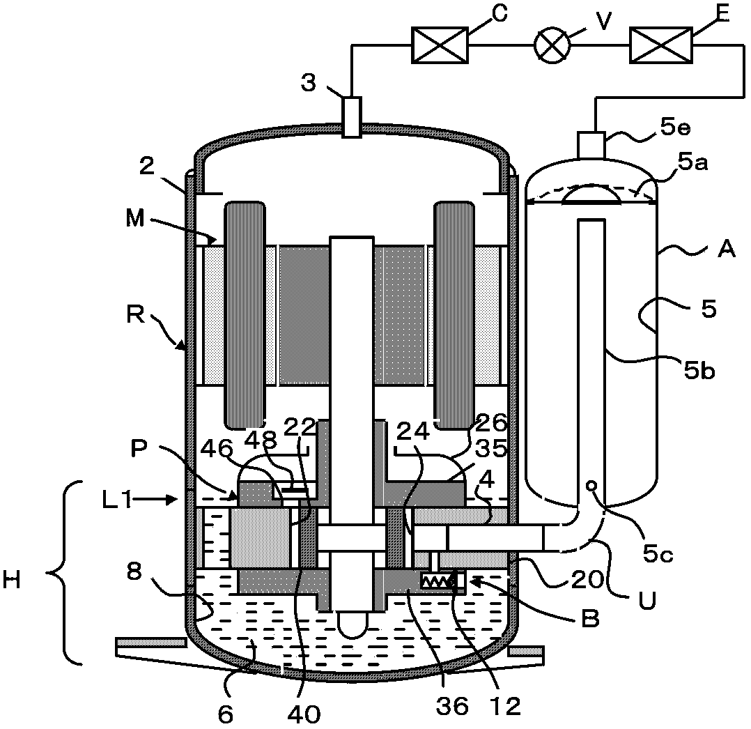
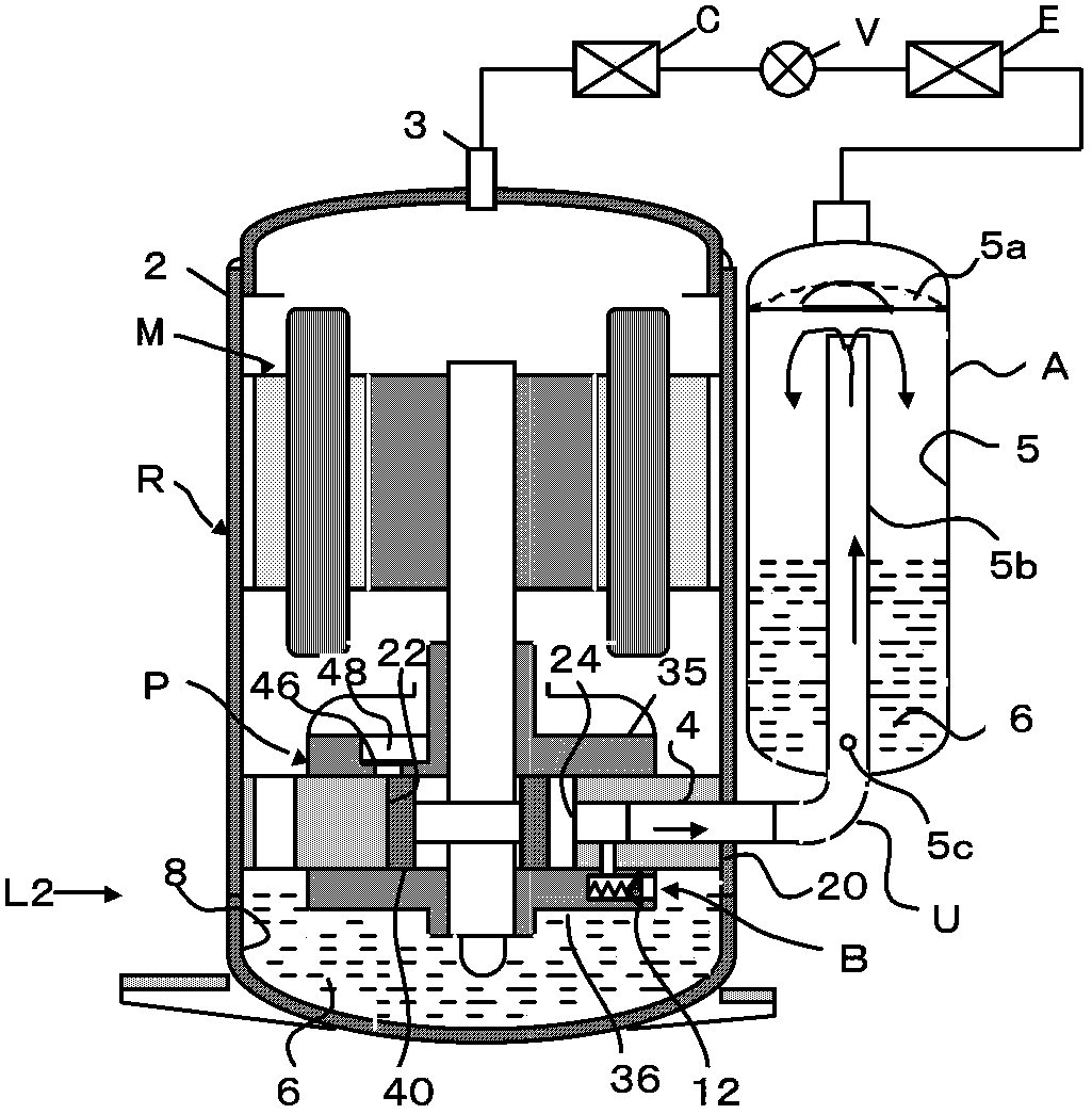
[0031] figure 1 It shows the structure of the rotary compressor R and the refrigeration cycle device. The compressor R includes: a motor M built in the airtight case 2, a rotary compression member P driven by the motor M, an oil storage chamber 8 provided at the bottom of the airtight case 2, and refrigerating machine oil 6 sealed in the oil storage chamber 8 (Hereinafter, simply referred to as oil or oil 6). H in the figure is the range of the oil storage chamber 8, and L1 is the position of the oil level. figure 1 The temperature of each part of the refrigeration cycle device and compressor is in a stable operation state, so the oil level (as L1) is sufficiently high. Furthermore, approximately 10 to 30% of the refrigerant is dissolved in the oil.
[0032] The side of the airtight casing 2 is equipped with an accumulator A, the compression chamber 22 of the compression part P and the accumulator A are connected through the suction pipe 4 . Therefore, the accumulator A, t...
Embodiment 2
[0055] Figure 9 In the shown embodiment 2, the L-shaped pipe 19 is connected to the inlet hole 16 of the bypass circuit B, and the opening position of the bypass circuit B is changed. As a result, the position of the oil level or the amount of oil after the compressor stops can be chosen arbitrarily. Figure 9 In the above embodiment, by adding the L-shaped pipe 19, the opening position suitable for the height of the sub-bearing 36 can be changed to near the upper surface of the cylinder 20.
[0056] In addition, even if the bypass circuit B is arranged on the flange portion of the main bearing 35, the opening position of the bypass circuit B can be changed to be close to the center of the cylinder 20 by using the L-shaped pipe 19 whose tip is opened on the lower side. In this embodiment, through such a simple operation, the arrangement location of the bypass circuit B and the position of the oil level after the compressor stops can be freely selected.
Embodiment 3
[0058] Figure 12 In the illustrated embodiment 3, the openings at both ends of the bypass circuit B are opened to the oil storage chamber 8 and the container 5 of the accumulator A. In addition, as a differential pressure valve device, the electric valve 60 should be arranged in the middle of the bypass circuit B. Therefore, after the compressor R is stopped, if there is a pressure difference between the airtight casing and the accumulator A, that is, if the electric valve 60 is opened between Δp>0, the oil 6 in the oil storage chamber 8 will be directly moved through the bypass circuit B. into container 5.
[0059] When restarting, regardless of Δp and operating time, if the electric valve 60 is closed, normal compression can be started. The length of the unloading time can be arbitrarily determined. The electric valve 60 is difficult to arrange in the airtight casing 2 like the differential pressure valve device of the first embodiment, but it is very advantageous in ter...
PUM
 Abstract
Description
Claims
Application Information
 - R&D
- Intellectual Property
- Life Sciences
- Materials
- Tech Scout
- Unparalleled Data Quality
- Higher Quality Content
- 60% Fewer Hallucinations
Browse by: Latest US Patents, China's latest patents, Technical Efficacy Thesaurus, Application Domain, Technology Topic, Popular Technical Reports.
© 2025 PatSnap. All rights reserved.Legal|Privacy policy|Modern Slavery Act Transparency Statement|Sitemap|About US| Contact US: help@patsnap.com


