
Injection head driving device for coiled tubing

A driving device and injection head technology, which is applied to drill pipes, casings, drill pipes, etc., can solve the problems of structural asymmetry, difficulty in hoisting and operation and installation, and poor balance, and achieve easy hoisting, operation and installation, and structural Compact, well-balanced effect

Active Publication Date: 2014-01-15
BC P INC CHINA NAT PETROLEUM CORP +2
View PDF8 Cites 4 Cited by
  • Summary
  • Abstract
  • Description
  • Claims
  • Application Information

AI Technical Summary

Problems solved by technology

[0008] In order to overcome the problems in the prior art that the hydraulic motor and the planetary gearbox are arranged on the same side of the injection head, resulting in structural asymmetry, resulting in poor balance, and making hoisting and installation difficult, the embodiment of the present invention provides a coiled tubing Injection head drive

Method used


Image

  • Injection head driving device for coiled tubing

Examples


Embodiment Construction

[0017] In order to make the object, technical solution and advantages of the present invention clearer, the implementation manner of the present invention will be further described in detail below in conjunction with the accompanying drawings.

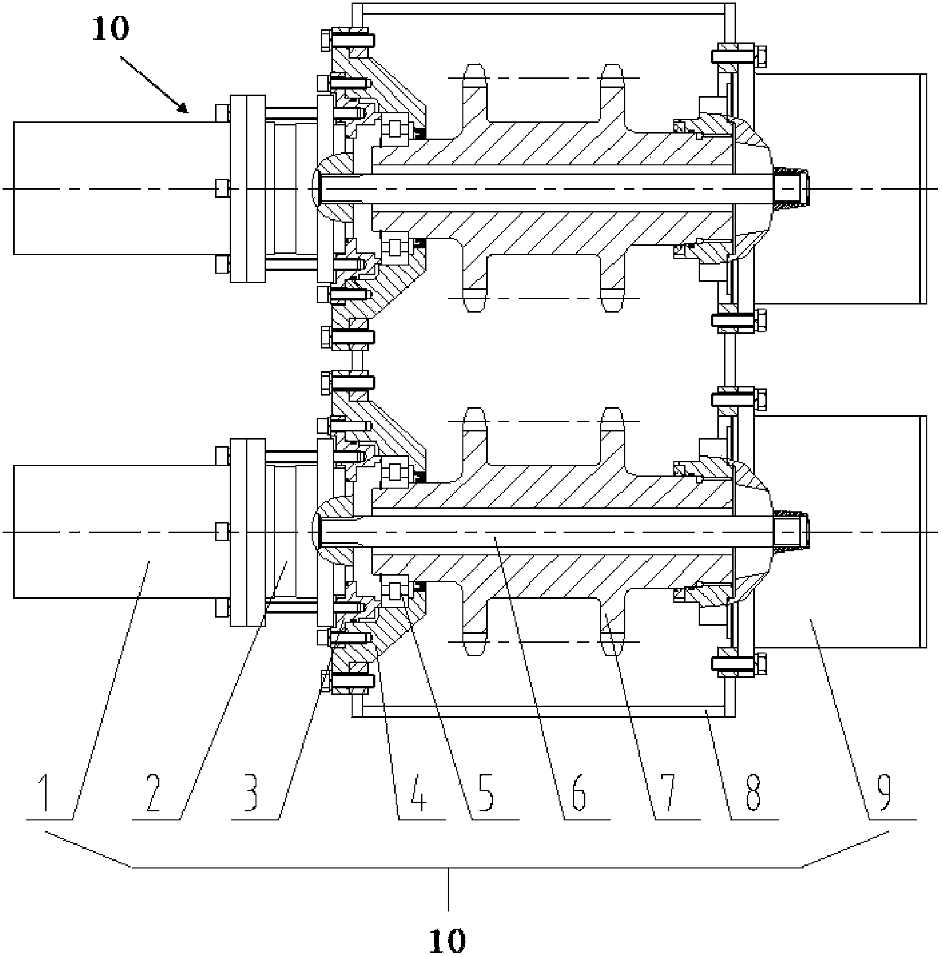
[0018] Such as figure 1 As shown, the embodiment of the present invention provides a coiled tubing injection head driving device, which includes two sets of hydraulic motor drive mechanisms 10 arranged on the injection head casing 8, and each set of hydraulic motor drive mechanisms 10 includes a hydraulic motor 1, a hydraulic Braking device 2, connecting disc 3, bearing seat 4, planetary gear reducer 9, bearing 5, sprocket shaft 7 and central shaft 6, the hydraulic motor 1 is connected with the hydraulic braking device 2 and installed on the connecting disc 3 Above, the connection plate 3 is fixed on one side of the injection head box 8 through the bearing seat 4, the bearing 5 is installed on the bearing seat 4, and the planetary gear...


PUM


Abstract

The invention discloses an injection head driving device for coiled tubing, and belongs to the field of petroleum. The injection head driving device for the coiled tubing comprises two sets of hydraulic motor driving mechanisms arranged in an injection head box body, and each set of hydraulic motor driving mechanism comprises a hydraulic motor, a hydraulic brake device, a connecting disc, a bearing block, a planetary reducer, a bearing, a sprocket shaft and a central shaft. The hydraulic motors and the planetary reducers are mounted on the two sides of the injection head box body respectively, the sprocket shafts are hollow shafts, the central shafts penetrates through the sprocket shafts, one end of each central shaft is connected with the output end of each hydraulic motor, and the other end of each central shaft is connected with the input end of each planetary reducer. The injection head driving device for the coiled tubing has the advantages of being compact and symmetrical in structure, good in balance performance, easy to lift, operate and mount, high in driving efficiency and good in low speed stability.

Description

technical field [0001] The invention relates to the field of coiled tubing drilling, well logging and workover operations, in particular to a coiled tubing injection head driving device. Background technique [0002] Coiled tubing equipment is a hydraulically driven workover equipment that can be used on offshore platforms as well as on land oilfields. Coiled tubing operation equipment is mainly composed of five parts: injection head (drive guide), drum, coiled tubing, operation room, power source, and blowout prevention system. [0003] Among them, the injection head (drive guide device) is a device for running the coiled tubing into the well or pulling the tubing out of the well. At present, there are mainly two structures of coiled tubing injection head driving devices. [0004] method one [0005] It is directly driven by a low-speed high-torque motor. In this driving mode, the motor is usually two-speed variable displacement. In order to meet the maximum lifting forc...

Claims


Application Information

Patent Timeline
Patent Type & Authority Applications(China)
IPC IPC(8): E21B19/22
Inventor 杨高刘寿军刘菲梁常飞陈立华熊革马青张富强
Owner BC P INC CHINA NAT PETROLEUM CORP
Learn More