
Top-reinforced cast-in-place concrete thin-wall pipe pile and construction method

A technology of thin-walled pipe piles and concrete, which is applied in the direction of sheet pile walls, foundation structure engineering, construction, etc., can solve the problems of pile body deviation, broken piles, and weak interlayers in the pile top area, and achieve good technical and economic benefits and ensure The effect of simple construction quality and construction process

Active Publication Date: 2015-05-27
HONGSHA CONSTR
View PDF7 Cites 0 Cited by
  • Summary
  • Abstract
  • Description
  • Claims
  • Application Information

AI Technical Summary

Problems solved by technology

[0005] However, in the actual construction process, since the cast-in-place concrete thin-walled pipe piles belong to the soil-squeezing pile type, the setting of adjacent pile sinking pipes and the movement of the pile driver will have adverse effects on the concrete piles that have not yet initially set. Even if the construction plan is optimized in terms of sequence, device penetration, etc., there will still be pile body deviation in the pile top area, or broken piles, pile concrete segregation, weak interlayer and other diseases, which will seriously affect the pile quality of cast-in-place thin-walled pipe piles and bearing capacity
[0006] At present, there is a thin-walled pipe pile, which includes a concrete pile body with a circular cross section, a reinforcement cage arranged in the concrete pile body, and an end plate and a hoop fixed at the end of the concrete pile body , although this type of pile has a simple structure, it can also restrain the deformation of the pile tip to a certain extent, but since the constraint is only set at the pile tip, it is difficult to effectively solve the problem of mutual extrusion deformation and failure between the pile bodies
[0007] To sum up, cast-in-place thin-walled pipe piles have the advantages of strong applicability, high bearing capacity, and good bending resistance. However, due to the large diameter and thin pipe wall of the pipe pile, some quality problems are likely to occur during construction, resulting in pile failure. It is difficult to effectively exert the bearing capacity of the body, which seriously affects the quality of the pile body and the effect of foundation treatment

Method used


Image

  • Top-reinforced cast-in-place concrete thin-wall pipe pile and construction method
  • Top-reinforced cast-in-place concrete thin-wall pipe pile and construction method
  • Top-reinforced cast-in-place concrete thin-wall pipe pile and construction method

Examples


Embodiment Construction

[0038] In this embodiment, the steel plate cutting and welding construction technical requirements, steel cage binding construction technical requirements, prefabricated pile tip design and construction technical requirements, vibrating immersed tube construction technical requirements, pile body concrete mix ratio design and pouring technical requirements, medium and coarse sand particles The technical requirements for filling construction, etc. will not be described repeatedly, and the embodiment of the structure related to the present invention will be focused on.

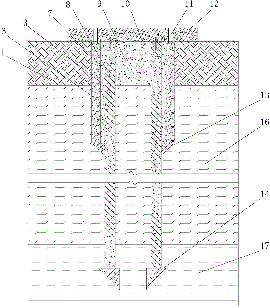
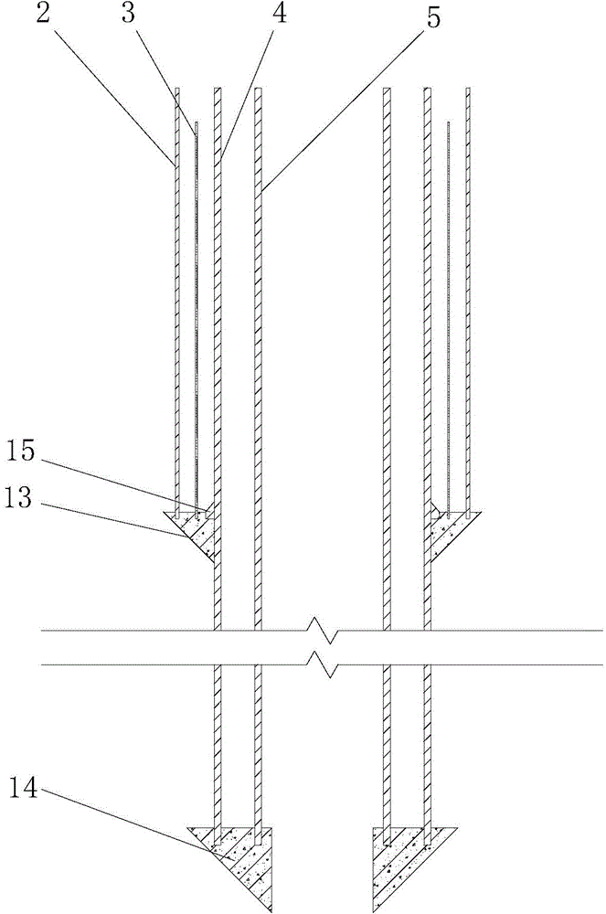
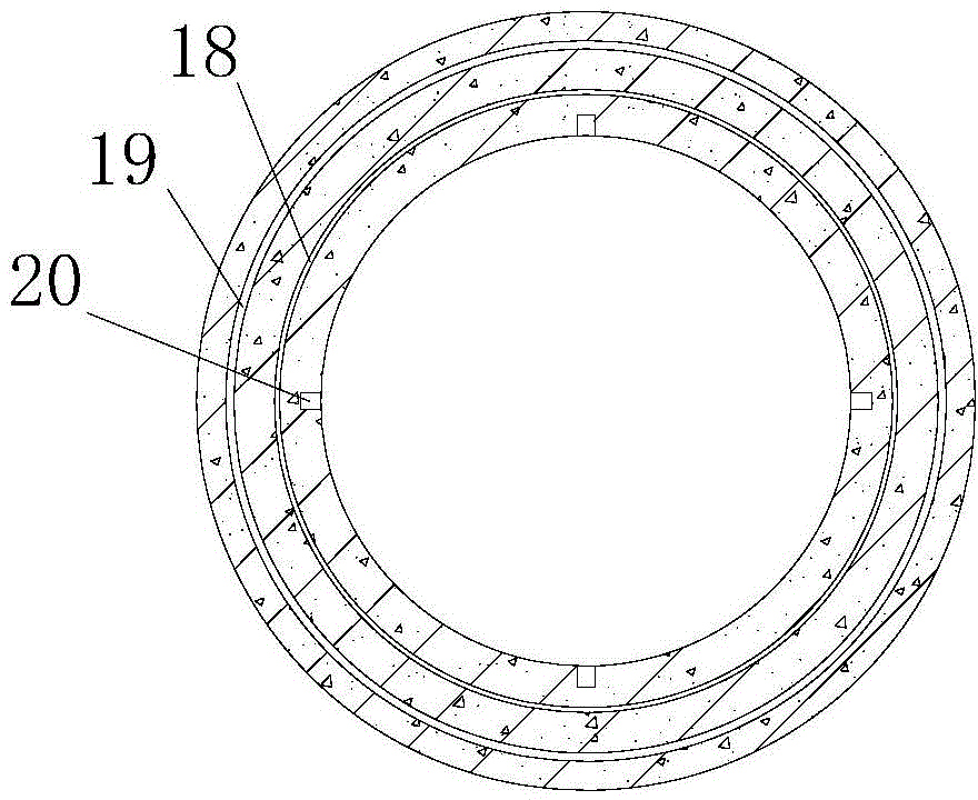
[0039] figure 1 It is a schematic diagram of a top-reinforced cast-in-place concrete thin-walled pipe pile of the present invention, figure 2 It is a schematic diagram of a top-reinforced cast-in-place concrete thin-walled pipe pile construction device of the present invention, image 3 It is a schematic diagram of the arrangement of notches on the upper surface of the upper prefabricated pile tip. refer to...


PUM


Abstract

The invention relates to a top-reinforced cast-in-place concrete thin-walled pipe pile, which is characterized in that the main body of the thin-walled pipe pile adopts double-layer steel sinking pipes to form a pile, the pile diameter on the upper part of the pile body is enlarged, and The outside of the concrete pile body of the enlarged section is provided with plastic sleeves and vertical drainage bodies in sequence from the inside to the outside; the enlarged section of the pile diameter is connected to the upper prefabricated pile tip, and the bottom of the pile body is connected to the lower prefabricated pile tip; the soil around the pile on the upper part of the thin-walled pipe pile The solidification treatment is to solidify the soil layer; connecting ribs are arranged between the top of the thin-walled pipe pile, the closed section of the pile core and the pile top cover plate; the drainage channel connected with the vertical drainage body is arranged in the pile top cover plate. The invention not only improves the driving quality of the pile body, but also improves the mechanical properties of the upper pile body and the soil around the pile, and at the same time prevents the deformation of the pile body caused by the mud belt coming out of the ground, and has better technical and economic benefits. The invention also discloses a construction method of the thin-walled pipe pile.

Description

technical field [0001] The invention relates to a cast-in-place thin-walled pipe pile, in particular to a top-reinforced cast-in-place concrete thin-walled pipe pile in which the upper part of the pile body is enlarged, a vertical drainage body is outsourced, and the pile top soil is solidified. The utility model belongs to the field of foundation treatment and is suitable for foundation treatment projects, especially for soft soil foundation treatment projects with shallow buried depth and small pile spacing. Background technique [0002] my country has a vast territory, complex geological conditions and large differences between regions, and there are many types of soft foundations, which are widely distributed, especially in coastal areas and inland lacustrine sedimentary facies areas. There are many complex medium-thick soft soil foundations. How to effectively improve the bearing capacity of deep soft soil foundations and control soil deformation has always been one of ...

Claims


Application Information

Patent Timeline
Patent Type & Authority Patents(China)
IPC IPC(8): E02D5/38E02D5/66E02D5/72
Inventor 张以国陈祥节林丰宋君勇谢纯良
Owner HONGSHA CONSTR
Learn More