A loom upper shaft manipulator

A technology of manipulators and looms, applied in the directions of manipulators, textiles, textiles and papermaking, can solve the problems of looms that cannot be placed, unfavorable arrangement of equipment, easy to roll and fall, etc. The effect of saving space

Active Publication Date: 2015-11-18
JIANGSU YOUCHENG CNC TECH CO LTD
View PDF5 Cites 0 Cited by
  • Summary
  • Abstract
  • Description
  • Claims
  • Application Information

AI Technical Summary

Problems solved by technology

The towel machine adopts two shafts, the upper wool shaft and the lower warp shaft. The upper wool shaft is installed at the upper part of the loom. When the upper wool shaft is unloaded, the forklift is usually used to lift the wool shaft to the installation position or put it on the ground. It takes a lot of space to turn and walk, which is not conducive to the arrangement of equipment in the loom workshop, causing some users to place their looms. As the diameter of the wool shaft on the loom becomes larger and heavier, the weight becomes heavier. When it is lifted, it is easy to roll and fall, which poses a considerable safety hazard

Method used


Image

  • A loom upper shaft manipulator

Examples


Embodiment Construction

[0020] The present invention will be further described below in conjunction with the accompanying drawings and embodiments.

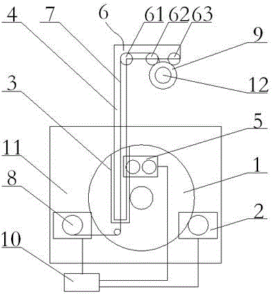
[0021] figure 1 As shown, a loom upper shaft manipulator includes a rotating seat 1, a rotating seat driving mechanism 2, a fixed slideway 3, a telescopic arm 4, a telescopic arm driving mechanism 5, a lifting pulley block 6, a reversing pulley 61, an intermediate pulley 62, a side Pulley 63, suspension rope 7, suspension rope retractable mechanism 8, ring suspension hook 9 and control electrical box 10. The two swivel seats 1 are arranged symmetrically on the left and right loom wallboards 11 on the upper part of the loom. Fixed slideway 3, the lower part of a telescopic arm 4 is installed in the fixed slideway 3, and the lower part of the telescopic arm 4 is connected with a telescopic arm drive mechanism 5 that drives the telescopic arm 4 to adjust sliding positioning along the fixed slideway 3, and the upper part of the telescopic arm 4 A sling 7 ...


PUM


Abstract

The invention relates to a weaving machine beam installing manipulator which comprises two rotating bases which are symmetrically arranged on a left wallboard and a right wallboard on the upper portion of a weaving machine, the rotating bases are connected with a rotating base driving mechanism, a fixed slide way parallel to the wallboards is formed in one rotating base, the lower portion of a telescopic arm penetrates through the fixed slide way, the lower portion of the telescopic arm is connected with a telescopic arm driving mechanism, a hang rope is connected to the telescopic arm in a penetrating mode in the telescopic arm direction, the lower end of the hang rope is connected with a hang rope pay-off and take-up mechanism, the upper end of the hang rope penetrates through a hosting pulley set on the upper portion of the telescopic arm and is connected with an annular lifting hook, and the rotating base driving mechanism, the telescopic arm driving mechanism and the hang rope pay-off and take-up mechanism are connected with a control electricity box. The telescopic arm rises and falls, the hang rope penetrates through the hosting pulley set, tensions and hoists a warp beam through the annular lifting hook, and installing of the warp beam is completed. The weaving machine beam installing manipulator is simple and compact in structure, does not occupy installation space of the weaving machine, saves putting space of the weaving machine and is beneficial to reasonable arrangement of the weaving machine and convenient and rapid to operate, and assembly and disassembly of the warp beam are stable and safe.

Description

technical field [0001] The invention relates to a loom component, in particular to a manipulator mechanism that can safely move the large and heavy wool warp beam of a towel loom between the ground and the rear upper part of the loom. Background technique [0002] Loom weaving can be divided into warp and weft motion, the warp direction includes horizontal take-up, warp let-off motion and vertical opening motion, warp let-off evenly sends warp yarns to interweave with weft yarns to form fabrics . The towel machine adopts two shafts, the upper wool shaft and the lower warp shaft. The upper wool shaft is installed at the upper part of the loom. When the upper wool shaft is unloaded, the forklift is usually used to lift the wool shaft to the installation position or put it on the ground. It takes a lot of space to turn and walk, which is not conducive to the arrangement of equipment in the loom workshop, causing some users to place their looms. As the diameter of the wool shaf...

Claims


Application Information

Patent Timeline
Patent Type & Authority Patents(China)
IPC IPC(8): B23P19/00B25J11/00D03J1/00
CPCD03J1/001
Inventor 王勇
Owner JIANGSU YOUCHENG CNC TECH CO LTD
Why Eureka
Try Eureka