Landfill gas collection and exhaust guide system of landfill

A technology for landfill gas and landfill, which is applied in the field of landfill gas collection, guidance and drainage systems, can solve problems such as obvious differences in landfill gas extraction and drainage flow, pressure imbalance, etc., so as to avoid difficulties in subsequent treatment and utilization, and The effect of reducing pollution

Active Publication Date: 2015-07-22
SHANGHAI MUNICIPAL ENG DESIGN INST GRP
View PDF3 Cites 0 Cited by
  • Summary
  • Abstract
  • Description
  • Claims
  • Application Information

AI Technical Summary

Problems solved by technology

[0009] The purpose of the present invention is to provide a landfill gas collection and drainage system to solve the pressure imbalance between the main gas pipelines of the gas collection wells in the existing landfill gas collection system and the difference in the flow rate of the landfill gas. Obvious problems, so as to realize the orderly management and rational development of landfill gas in the landfill, and reduce the pollution to the surrounding environment of the landfill

Method used


Image

  • Landfill gas collection and exhaust guide system of landfill
  • Landfill gas collection and exhaust guide system of landfill
  • Landfill gas collection and exhaust guide system of landfill

Examples


Embodiment 1

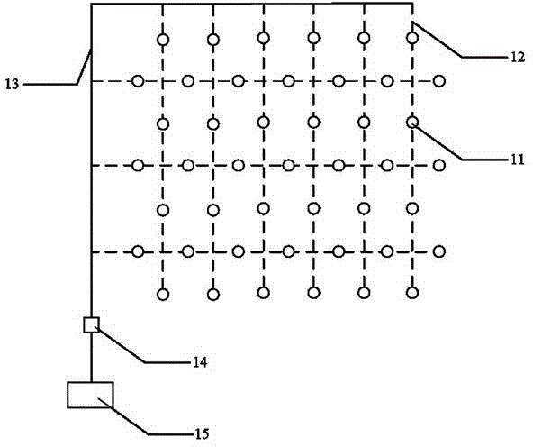
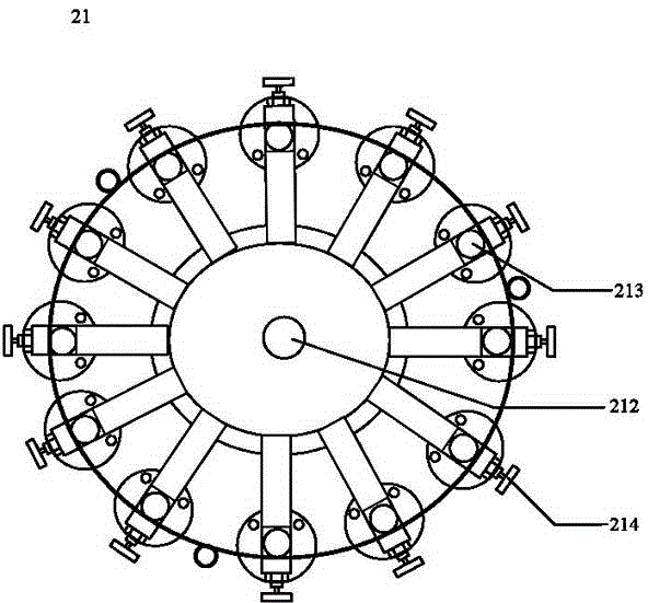
[0025] Such as figure 2 As shown, the landfill gas collection and drainage system 20 of the landfill in this embodiment includes: a plurality of gas gathering stations 21 arranged on the landfill, a gas transmission main pipe 22, an exhaust fan 23 and a landfill gas Centralized processing device 24. Each of the gas-gathering stations 21 includes a plurality of gas-gathering wells 211 and a main gas pipeline 212, and each of the gas-gathering wells 211 is connected to the gas pipeline through a gas-transmission branch pipe 213 and the gas pipeline 212 in turn. A gas main pipe 22, the gas transmission main pipe 22 is connected with the landfill gas central processing device 24 through the exhaust fan 23.

[0026] For each gas gathering station 21 , the connection with each gas gathering well 211 is realized through the main gas transmission pipe 212 and the gas transmission branch pipe 213 . Such as image 3 As shown, in order to ensure that each gas transmission main pipe 2...

Embodiment 2

[0032]The difference between this embodiment and Embodiment 1 is that a data processing center is added to the landfill gas collection and drainage system, and the methane concentration data of each gas collection well on the landfill is remotely transmitted to the data processing center. In this way, remote real-time monitoring of landfill gas collection is realized. The landfill gas collection and drainage system of this embodiment will be described in detail below, and the parts that are the same as those in Embodiment 1 will not be repeated.

[0033] Specifically, as Figure 5 and Figure 6 As shown, the landfill gas collection and drainage system 30 in this embodiment includes a plurality of gas gathering stations 31, and each of the gas gathering stations 31 includes a plurality of gas gathering wells 311 and a main gas pipeline 312, each The gas collection wells 311 are connected to the main gas transmission pipe 312 through a gas transmission branch pipe 313, and a m...


PUM


Abstract

The invention provides a landfill gas collection and exhaust guide system of a landfill, which comprises a plurality of gas collection stations arranged on the landfill, a gas transmission main pipe, a pumping exhaust fan and a landfill gas centralized treatment device, wherein each gas collection station comprises a plurality of gas collection wells and a gas transmission trunk pipe; each gas collection well is connected with the gas transmission main pipe sequentially by a gas transmission branch pipe and one gas transmission trunk pipe; the gas transmission main pipe is connected with the landfill gas centralized treatment device by the pumping exhaust fan; and a trunk pipe flow control valve is arranged on each gas transmission trunk pipe. With the adoption of the landfill gas collection and exhaust guide system of the landfill, the problems that pressure among gas transmission trunk pipes of gas collection wells of the existing landfill gas collection system is unbalanced, and a landfill gas pumping exhaust flow difference is obvious can be effectively solved, so that orderly management and reasonable development of landfill gas of the landfill are achieved, and pollution to a surrounding environment of a landfill area is reduced.

Description

technical field [0001] The invention relates to the technical field of garbage landfill, in particular to a landfill gas collection and drainage system for a landfill site. Background technique [0002] Landfill gas (LFG) is a gas produced by anaerobic fermentation or degradation of a large amount of organic components contained in garbage during the landfill process. The main components of landfill gas are methane (generally 40% to 65%) and carbon dioxide. At the same time, it contains trace amounts of toxic gases such as hydrogen sulfide, mercaptans, vinyl chloride, toluene, hexane, methyl chloride, and xylene. Landfill gas will pollute the surrounding atmospheric environment. Methane (molecular formula CH4) is not only a flammable and explosive gas, but also a strong greenhouse effect gas. Its equivalent volume has a potential value of greenhouse effect that is 21 times that of carbon dioxide. Relevant statistics show that methane emissions from landfills account for ab...

Claims


Application Information

Patent Timeline
Patent Type & Authority Patents(China)
IPC IPC(8): B09B3/00
Inventor 王艳明罗小勇陈思
Owner SHANGHAI MUNICIPAL ENG DESIGN INST GRP
Why Eureka
Try Eureka