
Full automatic electric induced abortion suction unit

A technology of artificial abortion and suction, which is applied in the field of medical equipment, can solve the problems of unclean suction and no change, and achieve the effect of reducing surgical sequelae and shortening the operation preparation time

Inactive Publication Date: 2014-01-15
杨星辰
View PDF0 Cites 3 Cited by
  • Summary
  • Abstract
  • Description
  • Claims
  • Application Information

AI Technical Summary

Problems solved by technology

[0002] With the continuous development of digital technology, many medical devices have begun to be controlled by embedded microcomputers, but whether it is the negative pressure suction device used in the existing superconducting flow visualizer or the separate electric abortion suction device and Any other type of electric suction device is a simple negative pressure suction device. The technology of this suction device has hardly changed in the past 30 years. During the process of artificial abortion or other suction operations, the surgeon must Constantly observe the pressure value of the negative pressure required for suction, so as to avoid medical accidents such as uterine perforation caused by excessive pressure or unclean suction caused by too low pressure, or when the pressure required for suction is not enough, manually start the negative pressure pump again. This has just brought a lot of inconvenience and distress to the doctor or patient in operation

Method used


Image

  • Full automatic electric induced abortion suction unit
  • Full automatic electric induced abortion suction unit

Examples


Embodiment Construction

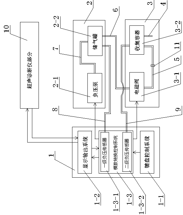
[0014] Such as figure 1 As shown, it is a fully automatic electric abortion suction device, including an automatic control system 1, a first-level negative pressure system 2 and a second-level negative pressure system 3, and the automatic control system 1 includes a keyboard control system 1-1, and an analog-to-digital conversion control system 1 -3, the display output system 1-2, the output end of the keyboard control system 1-1 is connected to the analog-to-digital conversion control system 1-3, the output end of the analog-to-digital conversion control system 1-3 is connected to the display output system 1-2, and the display The output end of the output system 1-2 is connected with the analog-to-digital conversion control system 1-3. The primary negative pressure system 2 includes a negative pressure pump 2-1 and an air storage tank 2-2, the secondary negative pressure system 3 includes a solenoid valve 3-1 and a collection container 3-2, and the collection container 3-2 is...


PUM


Abstract

The invention relates the field of medical instrument, and relates to a full automatic electric induced abortion suction unit, in particular to a full automatic electric induced abortion suction unit used in a pregnancy termination operation. The full automatic electric induced abortion suction unit comprises a collection container and a negative pressure pump. The collection container is connected with a first air pipe, the collection container is connected with an electromagnetic valve through a second air pipe, the electromagnetic valve is connected with an air storage tank through a third air pipe, and the air storage tank is connected with the negative pressure pump through a fourth air pipe. The suction unit further comprises an automatic control system. The automatic control system comprises a keyboard control system and an analog-digital conversion control system. An output terminal of the keyboard control system is connected with the analog-digital conversion control system. The analog-digital conversion control system comprises a first negative pressure sensor and a second negative pressure sensor. The first negative pressure sensor is connected with the air storage tank through a fifth air pipe and connected with the negative pressure pump. The second negative pressure sensor is connected with the collection container through a sixth air pipe and connected with the electromagnetic valve. The pressure of the full automatic electric induced abortion suction unit is not too large or too small.

Description

technical field [0001] The invention relates to the field of medical devices, in particular to a full-automatic electric abortion aspirator for terminating pregnancy. Background technique [0002] With the continuous development of digital technology, many medical devices have begun to be controlled by embedded microcomputers, but whether it is the negative pressure suction device used in the existing superconducting flow visualizer or the separate electric abortion suction device and Any other type of electric suction device is a simple negative pressure suction device. The technology of this suction device has hardly changed in the past 30 years. During the process of artificial abortion or other suction operations, the surgeon must Constantly observe the pressure value of the negative pressure required for suction, so as to avoid medical accidents such as uterine perforation caused by excessive pressure or unclean suction caused by too low pressure, or when the pressure r...

Claims


Application Information

Patent Timeline
Patent Type & Authority Applications(China)
IPC IPC(8): A61B17/42A61M1/00G05B19/04
CPCA61M1/00A61B2017/4216A61M2205/33A61M2205/3375A61M2205/50A61M2205/75A61M2210/1433
Inventor 不公告发明人
Owner 杨星辰
Learn More