Epicyclic reduction gear

A planetary gear reduction and planetary gear technology, applied in the field of planetary gear reduction devices, can solve the problems affecting the compactness of the planetary gear reduction device, inconvenient operation, poor stability, etc., and achieve the effect of easy operation, good stability and space assurance

Active Publication Date: 2014-01-08
SUMITOMO HEAVY IND LTD
View PDF8 Cites 4 Cited by
  • Summary
  • Abstract
  • Description
  • Claims
  • Application Information

AI Technical Summary

Problems solved by technology

[0008] However, in the structure disclosed in the above-mentioned Patent Document 1, a so-called dead gap occurs at an axial side portion other than the portion where the eccentric body shaft of the external gear is arranged, which affects the compactness of the entire planetary gear reduction unit.
[0009] Also, since the protrusions of the external gear are located on both sides in the axial direction, there is a problem of poor stability and inconvenient operation when the external gear is placed on the ground or a workbench.

Method used


Image

  • Epicyclic reduction gear
  • Epicyclic reduction gear
  • Epicyclic reduction gear

Examples


Embodiment Construction

[0021] Hereinafter, an example of the embodiment of the present invention will be described in detail with reference to the drawings.

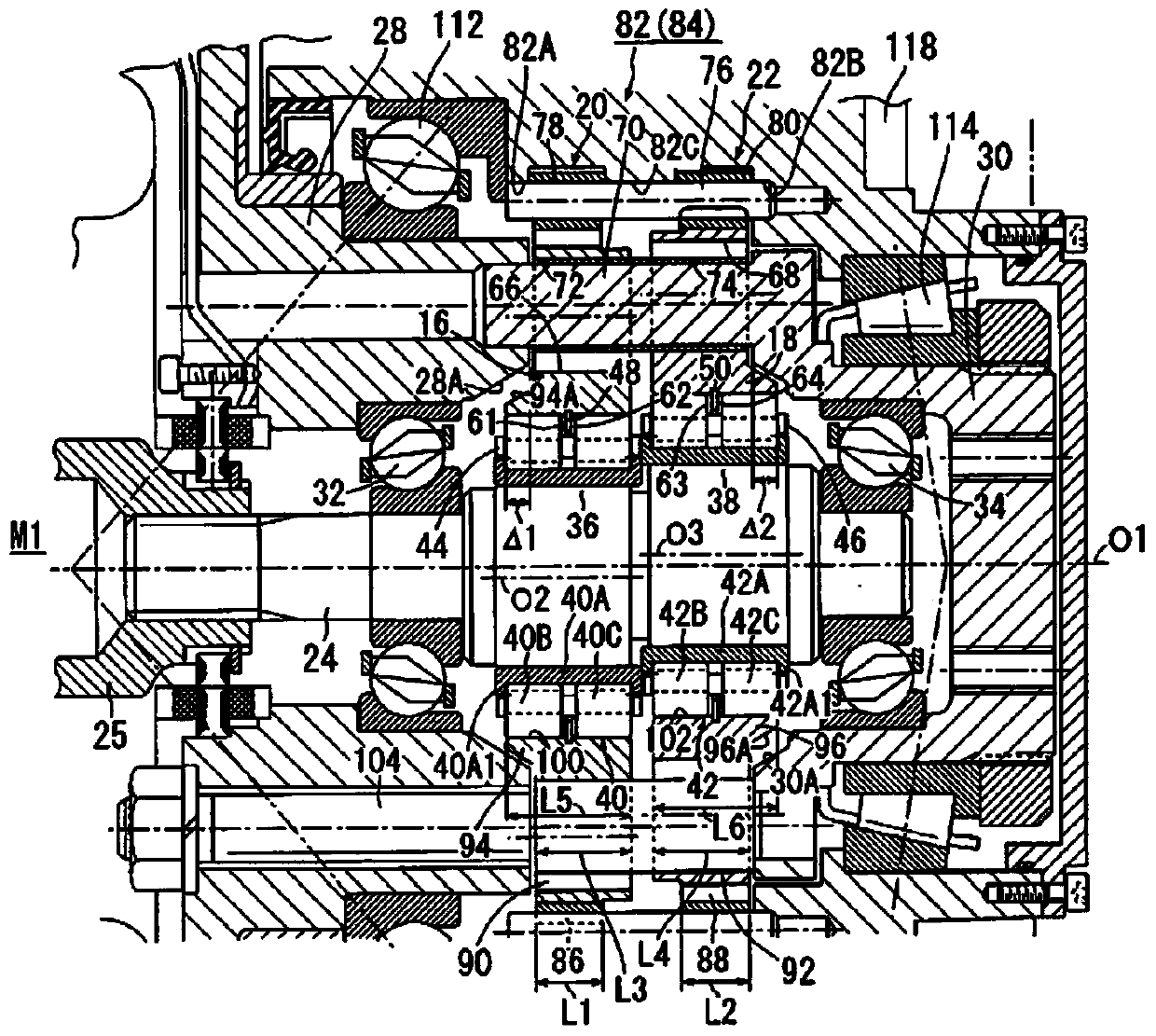
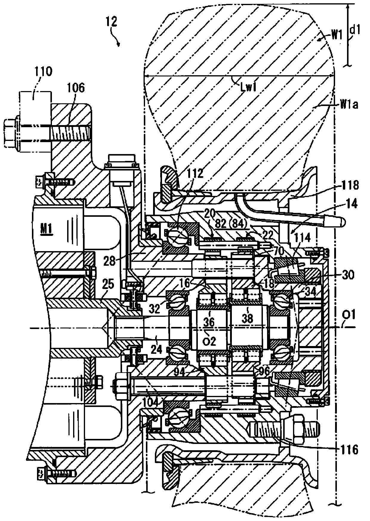
[0022] figure 1 It is a sectional view of main parts showing an example of an embodiment in which the eccentric oscillating planetary gear reduction device according to the present invention is applied to the wheel drive of a forklift, figure 2 is an overall sectional view of the planetary gear reduction unit.

[0023] The wheel W1 of the forklift (not shown in its entirety) 12 serves as a "fulcrum" for supporting cargo. Therefore, in order to make the position of the fork (not shown) constituting the "power point" or "action point" as close as possible to the ground contact point of the wheel W1, the outer diameter d1 of the wheel W1 should be as small as possible. In addition, in order to reliably bear the load of the cargo, the larger the volume of the tire portion (rubber portion) W1a of the wheel W1, the better. Therefore, only a very...


PUM


Abstract

In the present invention, the handling of an epicyclic gear is easy, a space at which a bearing provided with the size necessary to support the epicyclic gear is disposed can be reliably secured, and increased compactness of the overall epicyclic reduction gear can be further promoted. At the sides in the axial direction of a first and second epicyclic gear, the present invention has a first and second carrier member (28, 30) that synchronize the rotational components of the first and second epicyclic gear (16, 18). The first and second epicyclic gear (16, 18) have: a main body (90, 92) that contains teeth (86, 88) and that is supported by an eccentric body shaft (24) with a first and second roller bearing (40, 42) therebetween; and a protrusion (94, 96) that protrudes to only one side in the axial direction at the inner peripheral edge of the bearing hole (100, 102) at which the first and second roller bearing (40, 42) are disposed. The protrusions (94, 96) and the first and second carrier members (28, 30) overlap by ?1 and ?2 when seen from the diametral direction of the first and second epicyclic gears (16, 18).

Description

technical field [0001] The invention relates to a planetary gear reduction device. Background technique [0002] For example, Patent Document 1 discloses an eccentric oscillating type planetary gear speed reducer. This planetary gear reduction transmission includes an external gear (planetary gear) and an internal gear meshed with the external gear. The difference in the number of teeth between the external gear and the internal gear is set to be extremely small. [0003] This planetary gear reduction gear has a structure in which an eccentric body shaft having an eccentric body rotates, an external gear oscillates while being inscribed on an internal gear, and the relative rotation of the external gear to the internal gear is taken out from an output shaft. [0004] An eccentric body bearing is assembled between the eccentric body of the eccentric body shaft and the external gear, so that the external gear can swing and rotate smoothly on the outer periphery of the eccent...

Claims


Application Information

Patent Timeline
Patent Type & Authority Applications(China)
IPC IPC(8): F16H1/32B60K7/00
CPCB60K2007/0092B60K2007/0038F16H1/32B60K7/0007B60K17/043B60K7/00F16H57/08
Inventor 石塚正幸
Owner SUMITOMO HEAVY IND LTD
Why Eureka
Try Eureka