
Method and apparatus for particle separation

A particle and adjusting device technology, which is applied in solid separation, wet separation, and cyclone axial reversal devices, etc., can solve the problems of complex devices, low-quality separation, and unfavorable connections.

Active Publication Date: 2014-01-08
ECOMIN SRL
View PDF9 Cites 5 Cited by
  • Summary
  • Abstract
  • Description
  • Claims
  • Application Information

AI Technical Summary

Problems solved by technology

[0013] There are many cases where three or more by-products (e.g. metallurgical coal, heat extraction coal and slag) must be separated from the incoming material; for this purpose it may also be advantageous to use in these several stages Dense media with different densities instead of using completely separate separation stages which are much more expensive to install and operate, however if the difference between the two media is very high (e.g. dl=2.00kg / dm 3 ,d2=1.45kg / dm 3 ), it is unfavorable to connect each other
In fact, in this case, the fluid and its heavy medium (e.g., il=1.8kg / dm 3 ,d2=1.45kg / dm 3 ) will produce a density difference, resulting in at least a part of the next stage of the separator, the separator will not work under optimal operating conditions, resulting in a low quality separation or requiring an oversized stage
[0014] As may be noticed, on the one hand the use of a large number of separation stages theoretically allows the performance of the separation process to be optimized (in terms of separation accuracy if only two products are separated, or if three or more products are separated, then Involving cheapness), on the other hand the devices are made more complex, which practically means that they are functionally inflexible, since in order to maintain the design conditions of separation in several separation stages, it is impossible to carry out changes without affecting subsequent separation stages
[0015] Therefore, if for some reason it is assumed that the conditions of the fluid with suspended particles (such as flow velocity, density, etc.) change in one separation stage of the separator, even other separation stages will be involved, deteriorating the performance of the entire device

Method used


Image

  • Method and apparatus for particle separation
  • Method and apparatus for particle separation
  • Method and apparatus for particle separation

Examples


Embodiment Construction

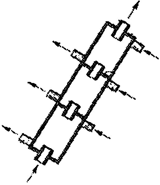
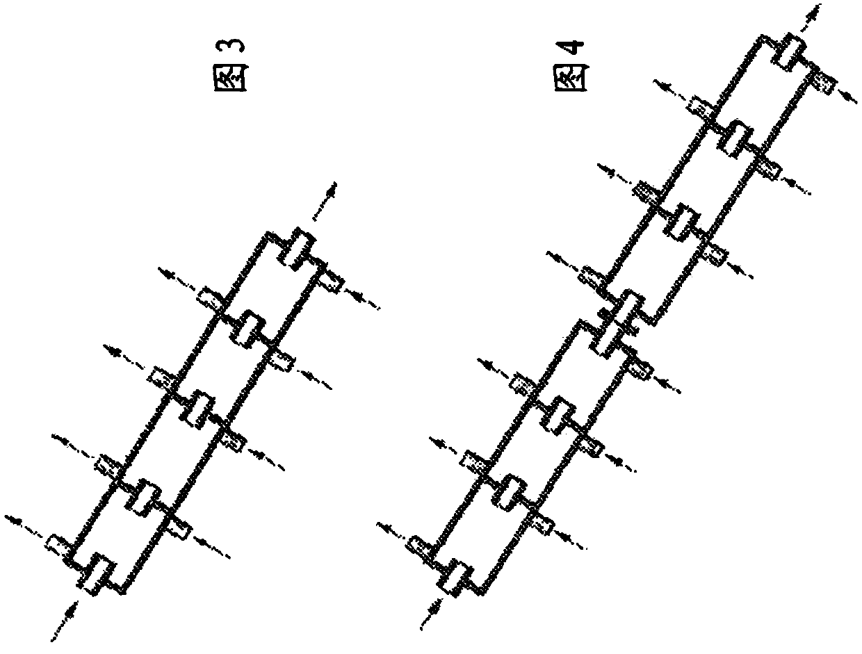
[0030] With reference to the drawings listed above and in particular Figures 5 to 10 , showing different embodiments of the separation device according to the invention; the first of these embodiments is at Figure 5 is denoted by 1 as a whole and it comprises two separation stages, wherein the first separation stage consists of a cyclone separator 2 and the second separation stage is a cylindrical separator 3 .

[0031] Since these types of separators are known per se, in this specification reference will only be made to those parts which are necessary for understanding the invention, other more detailed descriptions are referred to prior art, scientific literature and patents on the subject Published documents; among such published documents, in addition to the above-mentioned documents (IT1152915 and GB2164589), it is also pointed out that the patent published documents GB530309 or GB542988 related to cyclone separators are included.

[0032] Separator 1 is used in partic...


PUM


Abstract

The invention relates to the dynamic separation of particles such as those resulting from crushing and grinding extracted minerals or recycled materials (glass, plastic, etc.). The separation is carried out by multi-stage dynamic separators (2, 3), a regulation being carried out therebetween by feeding a fluid. This latter can be a dense medium similar to that feeding the stages, and can have a rotational component with respect to the axis of the separator.

Description

technical field [0001] The present invention relates to methods and devices for particle separation. Background technique [0002] The invention relates in particular to separations applied in the fields of mining, refining, etc., in which the particles to be separated obtained from ore reduced to a predetermined size are dispersed in a fluid which is fed into two dynamic separators, The two separators are usually two conical separators called cyclones, or cylindrical separators or a combination of these two shapes. [0003] A dynamic separator is a machine that utilizes centrifugal force generated by imparting rotational motion to a fluid containing those suspended particles within a chamber preferably having a cylindrical or frusto-conical geometry. [0004] Thus, the field of centrifugal force generated within this (gaseous or liquid) fluid causes the particles to be arranged in layers concentric with each other (depending on density, size, shape, etc.) Particles with t...

Claims


Application Information

Patent Timeline
Patent Type & Authority Applications(China)
IPC IPC(8): B03B5/34B04C5/26B04C7/00B04C11/00
CPCB04C5/26B03B5/34B04C7/00B04C11/00
Inventor 保罗·博赛图
Owner ECOMIN SRL
Learn More