Stator core coil axial adjustable brushless permanent magnet motor and control system thereof

A stator core and permanent magnet motor technology, applied in the direction of electronic commutation motor control, control system, motor control, etc., can solve the problems of reducing vehicle weight, high maintenance costs, unfavorable stable voltage, etc.

Inactive Publication Date: 2014-01-08
张贻强
View PDF4 Cites 7 Cited by
  • Summary
  • Abstract
  • Description
  • Claims
  • Application Information

AI Technical Summary

Problems solved by technology

[0004] Because in reality, the external force driving the generator rotor has uncontrollable factors (such as uncontrollable wind force in wind power generation, uncontrollable water flow in hydropower generation, etc.), or in a specific application, the driving generator rotor The drive of the generator is variable (for example, the variable change of the engine shaft in automobile power generation), so the voltage generated by the generator fluctuates greatly, which is not conducive to converting it into a stable voltage for daily use. In the existing technical solutions, a mechanical motor is installed on the rotor. The technical scheme of the gear transmission changes the speed ratio of the gear in time according to the change of the external force to ensure the stable speed of the rotor, but this scheme has the problems of heavy volume and high maintenance cost
Some technicians have also proposed the idea of ​​using a DC-DC converter to obtain a stable voltage, but the problem with this technical solution is that the voltage conversion efficiency of DC-DC under high current is not excellent, and the range of convertible input voltage is limited. , the reliability is poor, and the effect of practical application is not ideal
The other is a DC brushed excitation generator (Alternator). The internal combustion engine continues to run to drive the generator, and the rectified DC output is used to charge the battery and supply power to other systems. The coexistence of the two motors will undoubtedly increase the size and cost of the car, which is not conducive to Reduce the weight of the car, and work efficiency also needs to be improved

Method used


Image

  • Stator core coil axial adjustable brushless permanent magnet motor and control system thereof
  • Stator core coil axial adjustable brushless permanent magnet motor and control system thereof
  • Stator core coil axial adjustable brushless permanent magnet motor and control system thereof

Examples


Embodiment 1

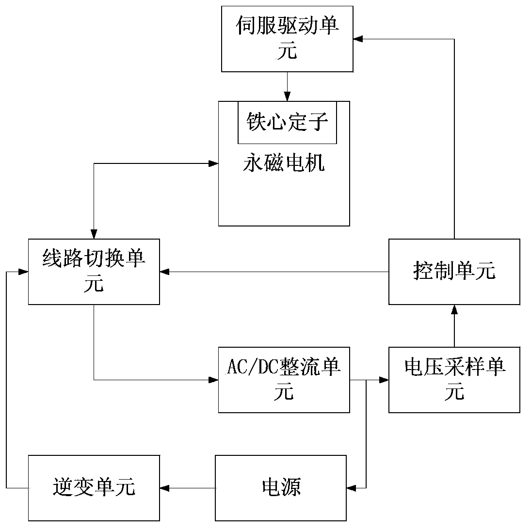
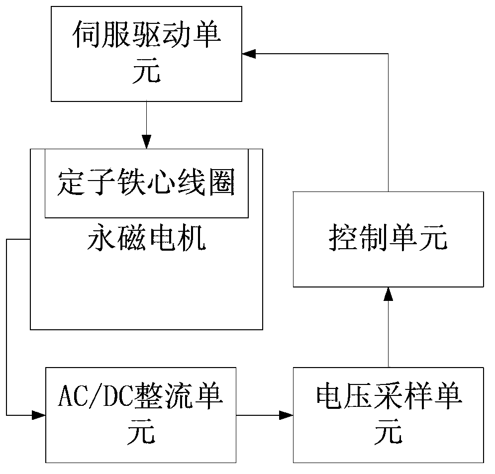
[0034] The embodiment of the present invention provides a brushless permanent magnet motor control system with axially adjustable stator core coil, such as figure 1 As shown, it includes: a permanent magnet motor, an AC / DC rectifier unit, a control unit, and a voltage sampling unit.

[0035] The permanent magnet motor is a brushless permanent magnet motor with axially adjustable stator core coils, which includes: a motor housing, a permanent magnet rotor rotatably installed in the motor housing, and a stator core composed of coils wound on the core Coil, the stator core coil can be axially moved on the inner wall of the motor housing, and the stator core coil is driven by a driving device to move axially along the inner wall of the motor housing to change the effective magnetic flux on the coil winding relative to the permanent magnet rotor . It can be understood that the manner in which the coils are wound on the iron core to form the stator core coils can be completed by th...

Embodiment 2

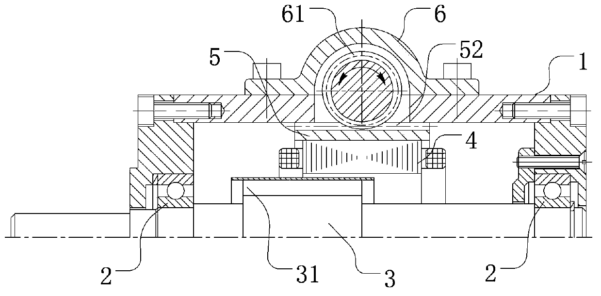
[0054] The embodiment of the present invention also provides a stator core coil axially adjustable motor control system, which differs from that in Embodiment 1 above in that the structure of the motor is slightly improved. Such as Figure 6 and Figure 7 As shown, in the embodiment of the present invention, the fixing device is still a hollow guide cylinder 5 with both ends open, and the stator core coil 4 is embedded in the hollow guide cylinder 5 and moves integrally with the hollow guide cylinder 5. The difference is that the drive connection part is The axial rack 52 arranged on the outer wall of the hollow guide cylinder does not need to increase the guide protrusions as in Embodiment 1, and only the tooth grooves are arranged axially on the outer wall of the hollow guide cylinder; It is a drive gear meshing with the axial rack.

[0055] In the embodiment of the present invention, the driving device drives the hollow guide cylinder to move. The standard name of this mo...

Embodiment 3

[0060] Such as Figure 8 As shown, the embodiment of the present invention is based on the stator core coil axially adjustable brushless permanent magnet motor control system in the above embodiment 1, an electronic commutator and a line switching unit are added, and the permanent magnet motor is connected through its phase line The line switching unit is also connected to the electronic commutator and the AC / DC rectifier unit respectively. The line switching unit receives the control signal from the control unit and selects to connect the permanent magnet motor and the electronic commutator or to connect the permanent magnet motor and the AC / DC rectifier. DC rectification unit.

[0061] Specific as Figure 9 As shown, the switching unit includes a first terminal J1 for connecting the phase line of the permanent magnet motor, a second terminal J2 for connecting the electronic commutator, and a third terminal for connecting the AC / DC rectifier unit Terminal J3, the first term...


PUM


Abstract

The invention discloses a stator core coil axial adjustable brushless permanent magnet motor and a control system of the core coil axial adjustable brushless permanent magnet motor. The motor comprises a motor shell, a permanent magnet rotor and a stator core coil, wherein the stator core coil can be axially movably installed on the inner wall of the motor shell. The system comprises the motor, an AC / DC rectification unit, a control unit and a voltage sampling unit. The voltage sampling unit acquires the output voltage of the AC / DC rectification unit and transmits the output voltage to the control unit, and the control unit controls the output quantity of a servo drive unit. The position of the stator core coil relative to the permanent magnet rotor is axially moved, and therefore the coil effective magnetic flux of the stator core coil is changed, the control unit in the power supply control system acquires the voltage output quantity of the motor to control the position of the stator core coil, and power generation output of the motor is fed back and adjusted. When the rotating speed of a rotor of the motor is higher than the nominal rotating speed and the rotating speed is dynamically rotated, stable voltage and power output when the brushless permanent magnet motor generates power can be achieved.

Description

technical field [0001] The invention relates to the technical field of permanent magnet motors, in particular to a brushless permanent magnet motor / generator and a control system thereof with axially adjustable stator core coils. Background technique [0002] Motor (English: Electric machine, commonly known as "motor") refers to an electromagnetic device that converts electrical energy into mechanical energy or mechanical energy into electricity (transmission) according to the law of electromagnetic induction. It is represented by the letter M (D in the old standard) in the circuit. When it is used as a motor, its main function is to generate driving torque and speed, as a power source for electrical appliances or various machinery. The permanent magnet motor needs to be driven by a controller; or it is called an electronic commutator (Electronic Commutator), which is represented by the letter G in the circuit as a generator. Its main function is to convert mechanical ene...

Claims


Application Information

Patent Timeline
Patent Type & Authority Applications(China)
IPC IPC(8): H02K29/00H02K1/18H02K5/18H02K7/116H02P6/00H02P9/00
CPCH02K21/024H02P6/34H02P2207/05
Inventor 张贻强张福兴
Owner 张贻强
Why Eureka
Try Eureka