Air conditioner

A technology for air conditioners and motors, applied in synchronous machines, refrigerators, compressors, etc., can solve the problems of weak excitation current, reduced heating capacity, and increased induced electromotive force of permanent magnets, and achieve the effect of changing the effective magnetic flux.

Inactive Publication Date: 2006-07-12
HITACHI LTD
View PDF0 Cites 0 Cited by
  • Summary
  • Abstract
  • Description
  • Claims
  • Application Information

AI Technical Summary

Problems solved by technology

However, there is a problem that the heating capacity decreases when the defrosting operation time is long
[0005] The method of widening the high-speed operating range using the field weakening control technique as described above has the limitation of heating and efficiency reduction due to the weakening of the field current
[0006] In addition, since the load of the defrosting operation is low, it is preferable to run at high speed during the heating operation to complete the defrosting operation, but there is a limit to the field weakening control due to the increase in the induced electromotive force of the permanent magnet

Method used


Image

  • Air conditioner
  • Air conditioner
  • Air conditioner

Examples


Embodiment Construction

[0026] Embodiments of the present invention will be described below.

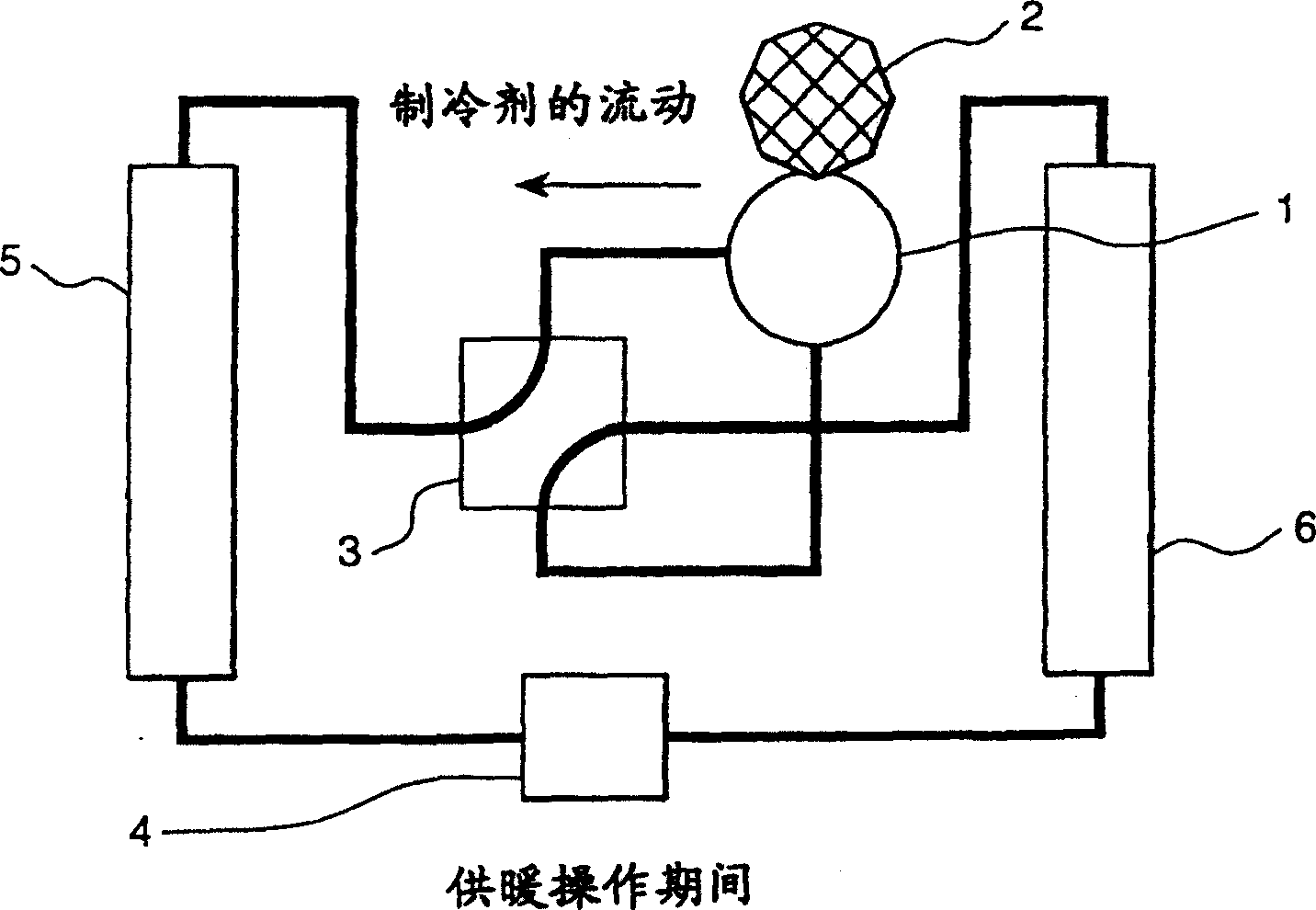
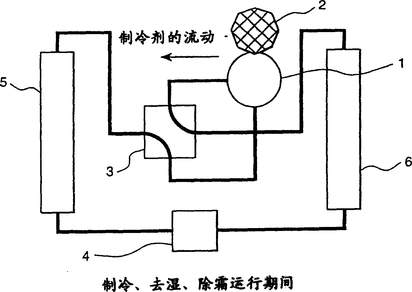
[0027] Fig. 1 is a schematic diagram showing a refrigeration cycle of an embodiment having a permanent magnet type synchronous motor.

[0028] FIG. 1( a ) shows a refrigeration cycle (flow of refrigerant) during a heating operation, and FIG. 1( b ) shows a refrigeration cycle during a cooling, dehumidification, and defrosting operation.

[0029] The air conditioner shown in Fig. 1 has the basic structure of refrigeration cycle, and this structure is by the electric motor 2 of compressor 1, the power source of compressor, a four-way valve 3, an expansion valve 4, an indoor heat exchanger 5 and an outdoor The heat exchanger 6 is configured to control the flow rate of the refrigerant cycle in the refrigeration cycle by changing the rotational speed of the motor and the opening degree of the electric expansion valve.

[0030] First, the refrigeration cycle during the heating operation shown in Fig. 1(a) will b...


PUM


Abstract

An air conditioner having a permanent magnet electric motor with a high output power characteristic in a cooling and heating range and a high output characteristic even in defrosting operation in a high-speed range.

Description

technical field [0001] The present invention relates to a motor using a permanent magnet for a magnetic field, more particularly, to a motor for driving an air conditioner and a method of controlling the motor, and to a motor whose rotor consists of a first field magnet and a The second field magnet configuration, the positions of the pole centers of the first field magnet and the second field magnet are changed according to the direction of torque, the effective magnetic flux density can be changed according to the speed of rotation, and a method of controlling the motor. Background technique [0002] In the prior art permanent field type motor, an induced electromotive force E is determined by a constant magnetic flux Φ generated by a permanent magnet disposed in a rotor and the rotational angular velocity ω of the motor. That is, when the rotational angular velocity ω (rotational speed) of the motor increases, the induced electromotive force increases proportionally. [...

Claims


Application Information

Patent Timeline
Patent Type & Authority Patents(China)
IPC IPC(8): H02K21/00F24F11/02F04B35/04F25B13/00F25B49/02H02K1/22H02K1/27H02K7/12H02K7/14H02K16/02H02K21/16H02K29/06
CPCH02K21/029F04B35/04F24F2011/0083F25B13/00F25B49/025H02K7/125H02K16/02H02K21/16F24F11/85
Inventor 金弘中能登原保夫
Owner HITACHI LTD
Why Eureka
Try Eureka