
Image magnification method and device

A technology in images and images, applied in the field of image processing, can solve the problems of image blur, loss, multi-frequency information, etc., to achieve the effect of good smoothness and maintain image clarity

Active Publication Date: 2014-01-08
HUAWEI TECH CO LTD
View PDF2 Cites 2 Cited by
  • Summary
  • Abstract
  • Description
  • Claims
  • Application Information

AI Technical Summary

Problems solved by technology

[0011] But in this method, the essence is to filter the image through a low-pass filter. The function of the low-pass filter is to let the low-frequency information pass and cut off the high-frequency information. Therefore, if the image is enlarged (generally speaking, When it exceeds 3 times), too much high-frequency information will be lost due to the effect of the low-pass filter, which will cause the image to appear blurred

Method used


Image

  • Image magnification method and device
  • Image magnification method and device
  • Image magnification method and device

Examples


Embodiment Construction

[0034] In the following description, for purposes of illustration rather than limitation, specific details, such as specific system architectures, interfaces, and techniques, are set forth in order to provide a thorough understanding of the present application. It will be apparent, however, to one skilled in the art that the present application may be practiced in other embodiments without these specific details. In other instances, detailed descriptions of well-known devices, circuits, and methods are omitted so as not to obscure the description of the present application with unnecessary detail.

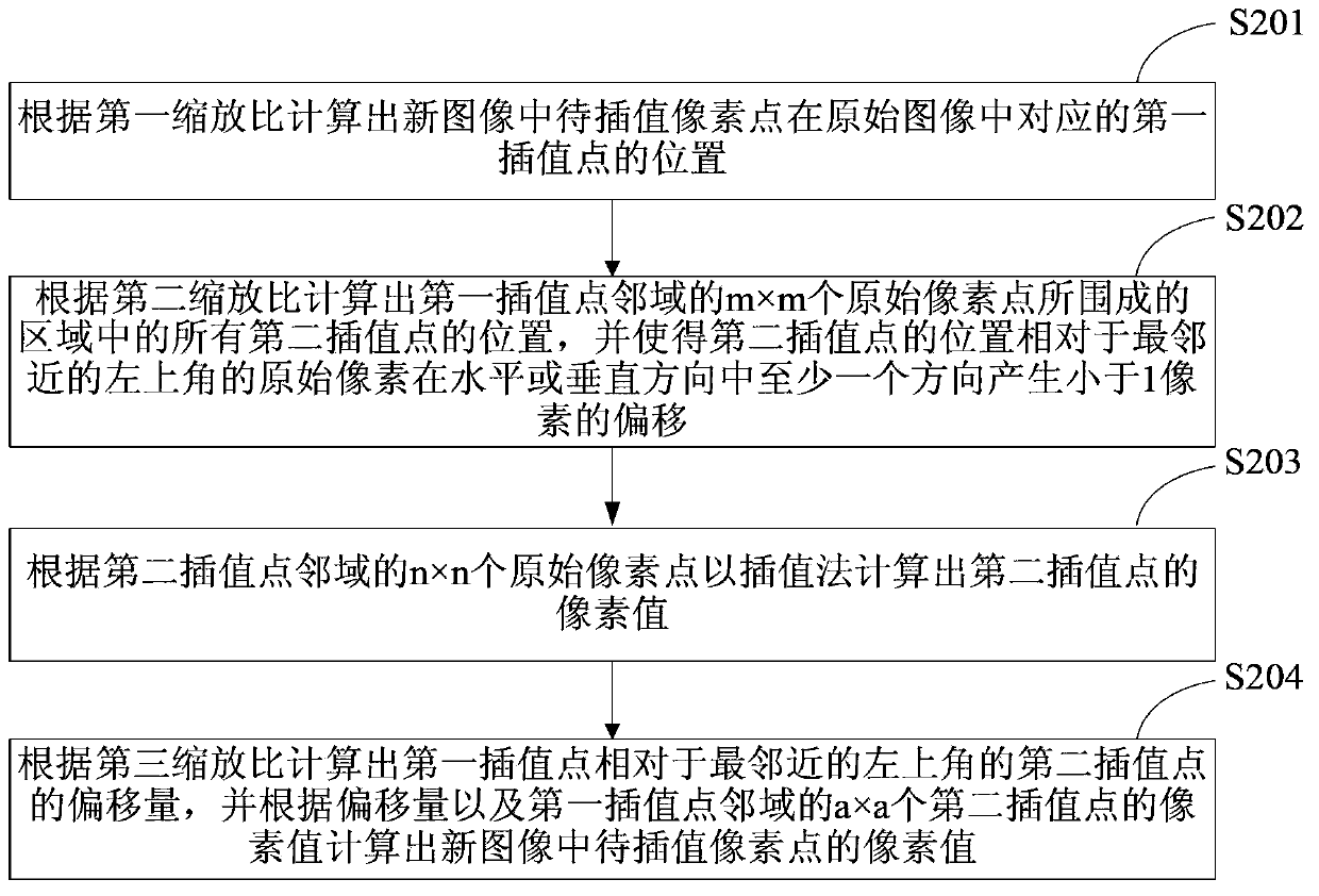
[0035] refer to figure 2 , figure 2 It is a flowchart of an embodiment of the image enlargement method of the present application. The image enlargement method of this embodiment is used to zoom the original image to obtain the image of the target size, including the following steps:

[0036] S201: Calculate the position of the first interpolation point corresponding to the pi...


PUM


Abstract

The invention discloses an image magnification method and device. The method comprises the steps of calculating the positions, corresponding to first interpolating points in an original image, of pixel points to be interpolated in a new image according to a first pantograph ratio; calculating the positions of all second interpolating points in a region surrounded by m*m original pixel points in an adjacent region of the first interpolating points according to a second pantograph ratio, and enabling the positions, relative to the original pixels at the nearest upper left corner, of the second interpolating points to generate offset smaller than one pixel in the at least one direction of the horizontal or perpendicular directions, wherein the second pantograph ratio is two; calculating the pixel values of the second interpolating points according to n*n original pixel points in the adjacent region of the second interpolating points; calculating the offset amount, relative to the second interpolating points at the nearest upper left corner, of the first interpolating points according to a third pantograph ratio, and calculating the pixel values of the pixel points to be interpolated according to the offset amount and the pixel values of the a*a second interpolating points in the adjacent region of the first interpolating points, wherein the third pantograph ratio is equal to the result that the first pantograph ratio is divided by the second pantograph ratio.

Description

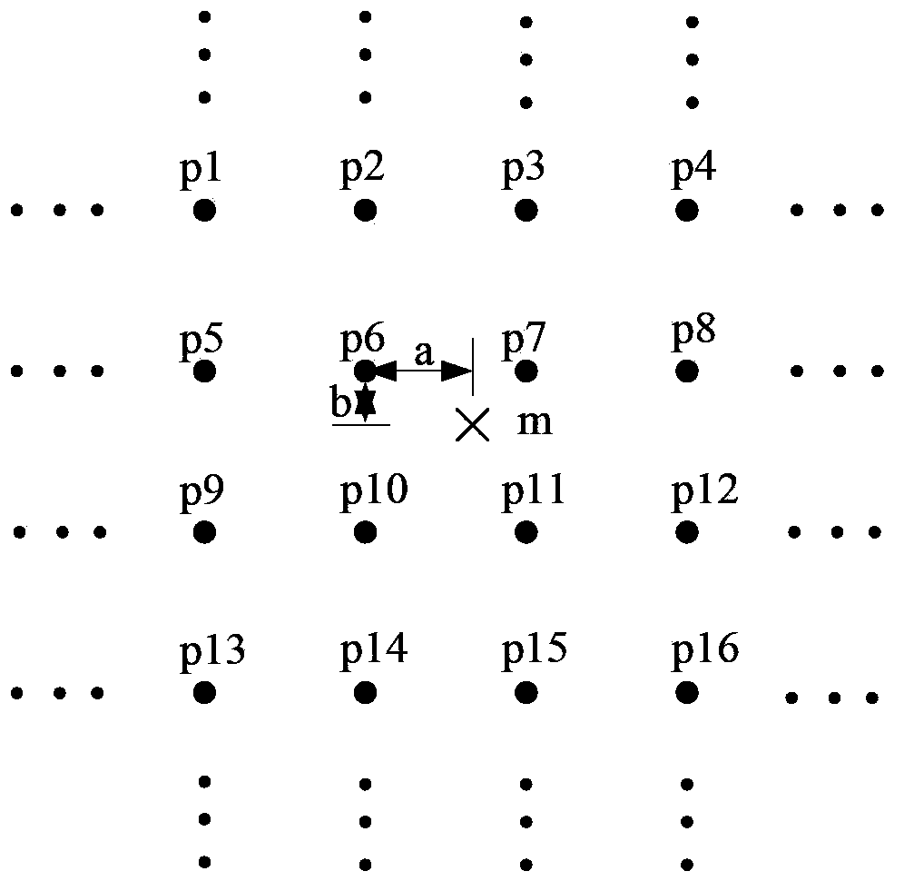
technical field [0001] The present application relates to the field of image processing, especially an image enlargement method and device. Background technique [0002] Nowadays, more and more electronic devices support high-resolution display. In order to make the smaller original image fit for the high-resolution display of the electronic device, the image must be enlarged. [0003] The prior art provides an image magnification method. Firstly, the zoom ratio is obtained by obtaining the multiple that needs to be zoomed in on the original image, and then the interpolation point corresponding to the pixel to be interpolated in the new image in the original image is calculated according to the zoom ratio. Finally, according to The pixel values ​​of the pixel points in the neighborhood of the interpolation point are interpolated to calculate the pixel value of the pixel point to be interpolated corresponding to the interpolation point. [0004] refer to figure 1 , taking t...

Claims


Application Information

Patent Timeline
IPC IPC(8): G06T3/40
Inventor 朱舸
Owner HUAWEI TECH CO LTD
Learn More