
System and circuit for high-precision measuring of resistor and capacitor

A technology for measuring resistance, resistance and capacitance, applied in the direction of measuring resistance/reactance/impedance, measuring electrical variables, measuring devices, etc., can solve the problems of low measurement accuracy, poor flexibility, and high price, and achieve high clock frequency, accelerated rise and Effect of decreasing speed and increasing measurement speed

Inactive Publication Date: 2014-01-08
HUBEI UNIV OF TECH
View PDF8 Cites 12 Cited by
  • Summary
  • Abstract
  • Description
  • Claims
  • Application Information

AI Technical Summary

Problems solved by technology

[0005] The purpose of the embodiments of the present invention is to provide a system and circuit for measuring resistance and capacitance with high precision, aiming to solve the existing problems of complex circuits, poor flexibility, low measurement accuracy and high price

Method used


Image

  • System and circuit for high-precision measuring of resistor and capacitor
  • System and circuit for high-precision measuring of resistor and capacitor

Examples


Embodiment Construction

[0028] In order to make the object, technical solution and advantages of the present invention more clear, the present invention will be further described in detail below in conjunction with the examples. It should be understood that the specific embodiments described here are only used to explain the present invention, not to limit the present invention.

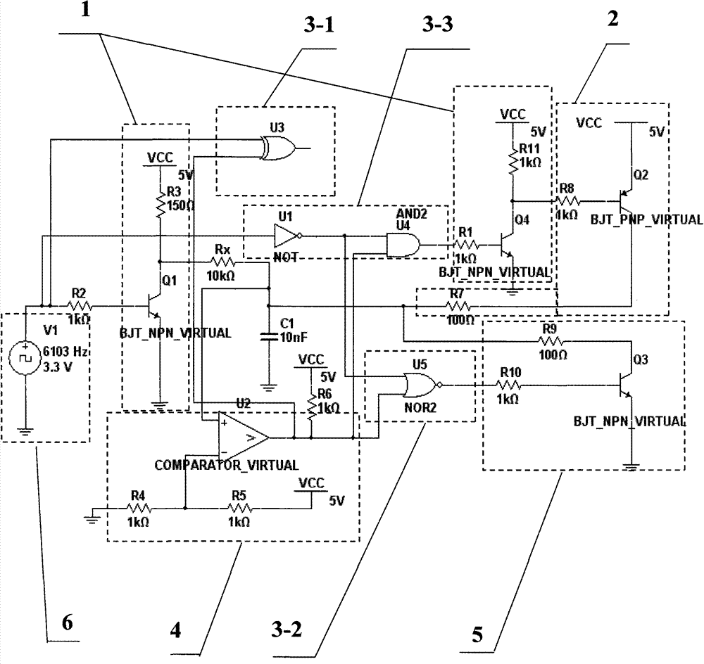
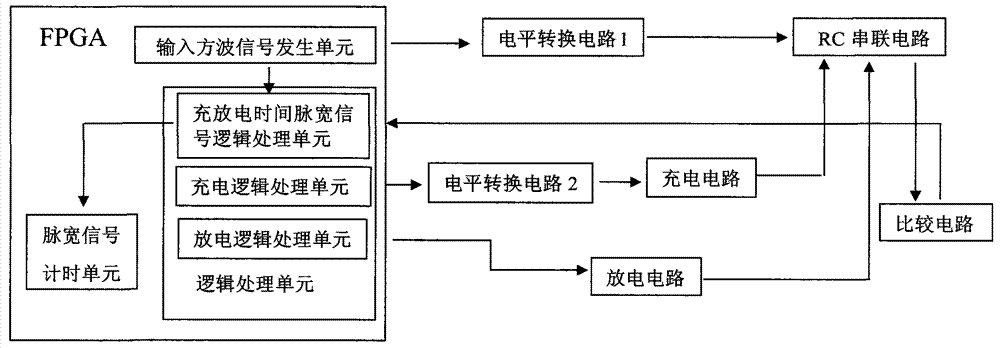
[0029] figure 1 The system and circuit structure for measuring resistance and capacitance with high precision provided by the present invention are shown. For ease of illustration, only the parts relevant to the present invention are shown.

[0030] The system for measuring resistance and capacitance with high precision in the embodiment of the present invention, the system for measuring resistance and capacitance with high precision includes: an input square wave signal generating unit, a level conversion circuit unit, a secondary charging circuit unit, a secondary discharging circuit unit, and a logic processing Unit, c...


PUM


Abstract

The invention relates to a system for high-precision measuring of a resistor and a capacitor. The system comprises an input square wave signal generating unit, a level conversion circuit unit, a secondary charging circuit unit, a secondary discharging circuit unit, a logic processing unit, a comparison circuit unit, and a pulse width signal timing unit. The system has the advantages that the RC (resistor and capacitor) charging and discharging time is measured, the purpose of measuring the resistors and the capacitors is realized, and the secondary charging circuit, the secondary discharging unit and the logic processing are additionally arranged on the basis of the RC charging circuit and the RC discharging circuit, so the ascending and descending speed of the output signal is improved, and the single measuring speed is improved; the clock frequency of pulse counting is high, the ns-level measurement of time resolution is realized, the clock frequency is doubled to 200M by an FPGA (field programmable gate array), and the time resolution is 5ns; when the resistor is measured, the larger capacitor is selected to improve the ratio coefficient of pulse counting value to the resistor R is improved, or when the capacitor is measured, the larger resistor is selected to improve the ratio coefficient of pulse counting value to the capacitor C, so the measuring precision and the resolution are improved.

Description

technical field [0001] The invention belongs to the technical field of measuring electronic components, in particular to a system and circuit for measuring resistance and capacitance with high precision. Background technique [0002] With the development of the electronics industry, the application of resistance and capacitance components has increased dramatically, and the scope of application has become wider and wider. Its parameters are tested in many applications. [0003] At present, the main method of measuring resistance is the bridge method, and its basic idea is to convert the resistance value into a voltage value or a frequency value. As long as the AD converter measures the voltage at both ends of the measured resistance, and then undergoes corresponding calculations. This measurement method has a simple structure, but it is affected by the input voltage of the AD converter, the conversion accuracy and the output frequency range. This method has a small measure...

Claims


Application Information

Patent Timeline
IPC IPC(8): G01R27/02G01R27/26
Inventor 王选择曾志祥杨练根翟中生范宜艳
Owner HUBEI UNIV OF TECH
Learn More