
Vibration reduction testing device for chip type micro-gyroscope

A test device and gyroscope technology, which is applied in the direction of vibration test, measurement device, machine/structural component test, etc., can solve the problem of real-time application of micro gyroscopes that cannot meet the mass production, difficult adjustment of resonance frequency of vibration reduction system, and installation of vibration reduction test mechanism Complexity and other issues, to achieve the effect of simple structure, easy processing and assembly, and easy preparation

Active Publication Date: 2014-01-08
NANJING UNIV OF SCI & TECH
View PDF8 Cites 9 Cited by
  • Summary
  • Abstract
  • Description
  • Claims
  • Application Information

AI Technical Summary

Problems solved by technology

At present, the vibration reduction test mechanism of the chip type micro gyroscope is complicated to install, cumbersome to operate, difficult to process, and the resonance frequency of the vibration reduction system is not easy to adjust, which cannot meet the requirements of mass production and real-time application of micro gyroscopes.

Method used


Image

  • Vibration reduction testing device for chip type micro-gyroscope
  • Vibration reduction testing device for chip type micro-gyroscope
  • Vibration reduction testing device for chip type micro-gyroscope

Examples


Embodiment Construction

[0013] The present invention will be described in further detail below in conjunction with the accompanying drawings and specific embodiments.

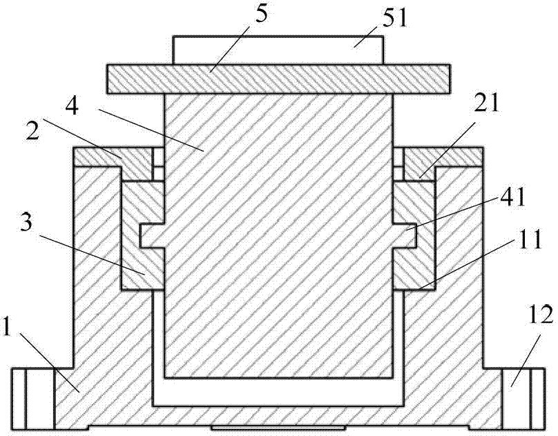
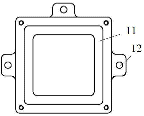
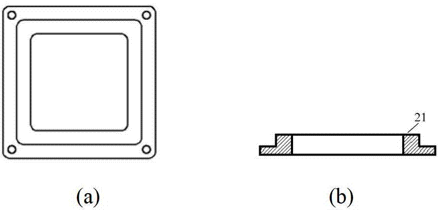
[0014] combine figure 1 , the vibration reduction test device of the chip type micro-gyroscope of the present invention is used to carry out the vibration reduction test of the chip type micro-gyroscope. It is fixed on the vibrating table through the installation hole 12 provided at the bottom. The inner wall of the cavity of the plastic box 1 is provided with a first boss 11 surrounding the inner wall, and the middle position of the outer wall of the mass block 4 is provided with a second boss 41 surrounding the outer wall to reduce vibration. The rubber 3 is provided with an assembly groove that matches the second boss 41. After the assembly of the mass block 4 and the damping rubber 3, it is placed on the first boss 11 in the cavity of the rubber box 1. The middle of the rubber cover 2 has a hole and Set up with the rubber box 1, ...


PUM


Abstract

The invention discloses a vibration reduction testing device for a chip type micro-gyroscope. The device comprises a rubber box, a rubber cover, a vibration reduction rubber, a mass block and a substrate, wherein the rubber box is fixed on a vibration table through installing holes arranged in the bottom of the rubber box, the inner wall of the cavity of the rubber box is provided with a first boss encircling the inner wall, a second boss encircling the outer wall of the mass block is arranged at a middle position of the outer wall, the vibration reduction rubber is provided with an assembling groove cooperating with the second boss, the mass block and the vibration reduction rubber are assembled together and then arranged in the cavity of the rubber box, the center of the rubber cover is perforated and arranged to be cooperative with the rubber box, the mass block passes through the central hole in the rubber cover, the interior surface of the rubber cover is provided with a third boss along the edge of the central hole, the third boss is pressed on the vibration reduction rubber, the substrate is fixedly arranged on the top of the mass block, and the upper surface of the substrate is provided with two fourth projecting blocks used for fixing the chip type micro-gyroscope. The vibration reduction testing device for the chip type micro-gyroscope has the advantages of a simple structure, convenient installation and adjustable frequency and meets requirements for batch production.

Description

technical field [0001] The invention relates to the technical field of vibration testing, in particular to a vibration-reduction testing device for a chip-type micro-gyroscope. Background technique [0002] Chip-type micro-gyroscope is a typical MEMS inertial sensor. The sensor structure is prepared by microelectronics processing technology, and the measurement and control circuit is prepared by ASIC. It has the advantages of mass production and so on, and has broad application prospects in both military and civilian fields. In civilian use, it is mainly used in the automotive industry, industrial monitoring and consumer products and robotics, such as airbags, anti-lock braking systems, yaw rate sensors, roll rate sensors, image stabilization and toys, etc.; in the military field, mainly Autonomous navigation and guidance systems for smart bombs, smart shells, tactical missiles, new concept weapons and micro-aircraft, etc. [0003] The working environment of the chip-type ...

Claims


Application Information

Patent Timeline
Patent Type & Authority Applications(China)
IPC IPC(8): G01C25/00G01M7/02
CPCG01C25/005G01M7/025G01M7/027
Inventor 施芹裘安萍夏国明苏岩丁衡高
Owner NANJING UNIV OF SCI & TECH
Learn More