
Gas-assisted extrusion equipment with stirring and pushing functions

An extrusion equipment and gas-assisted technology, applied in the field of plastic thermal processing equipment, can solve the problems of large rotational torque, large die pressure drop, increased energy consumption, etc., and meet the requirements of reducing screw rotational torque and extrusion expansion. ratio, the effect of reducing frictional resistance

Inactive Publication Date: 2014-01-08
昆山市华浦塑业有限公司
View PDF2 Cites 1 Cited by
  • Summary
  • Abstract
  • Description
  • Claims
  • Application Information

AI Technical Summary

Problems solved by technology

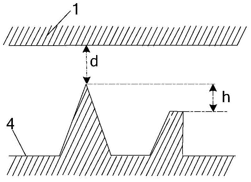
The thread of the screw directly affects the ejection effect of the molten plastic body. The thread height (1 / 2 of the difference between the major diameter and the small diameter of the thread) is too high, which requires a large rotational torque, and the thread height is too low. The push-out speed of the plastic body is slow or even reverse glue occurs, which causes the blockage of the barrel
In addition, due to the resistance between the extrusion die and the extrusion melt, the existing extrusion molding technology generally has the problem of extrusion swell, that is, the cross-sectional size of the extruded product is larger than the size of the extrusion die, and the extrusion swell This greatly increases the difficulty in the design of the extrusion die, which affects the accuracy of the product. At the same time, due to the high viscosity of the molten plastic material, a large die pressure is required to overcome the resistance of the inner wall of the die to the extrudate during extrusion, resulting in a pressure drop in the die. Large, so that the internal stress of the extruded product increases, resulting in increased deformation, but also increases energy consumption, affecting the quality of plastic products

Method used


Image

  • Gas-assisted extrusion equipment with stirring and pushing functions
  • Gas-assisted extrusion equipment with stirring and pushing functions

Examples


Embodiment Construction

[0024] The following is a clear and complete description of the technical solutions in the embodiments of the present invention in conjunction with the accompanying drawings of the present invention. Obviously, the described embodiments are only part of the embodiments of the present invention, not all of them. Based on the embodiments of the present invention, all other embodiments obtained by persons of ordinary skill in the art without creative efforts fall within the protection scope of the present invention.

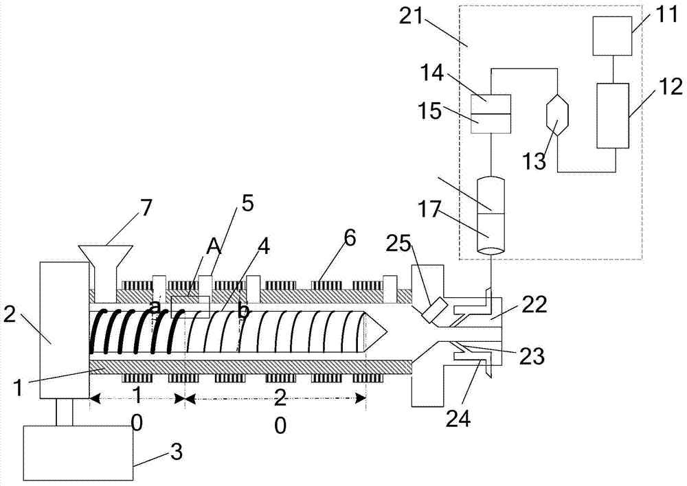
[0025] See figure 1 and figure 2 , a gas-assisted extrusion device with a stirring and pushing function in this embodiment includes: an extruder, an extruder head connected with the extruder, wherein the extruder includes a barrel 1, a driving motor 3 and reducer 2, the feed end of the barrel 1 is provided with a feed port, the discharge end of the barrel 1 is connected to the discharge die, the barrel 1 is provided with a screw 4, and the screw 4 can rotate in th...


PUM


Abstract

The invention discloses gas-assisted extrusion equipment with stirring and pushing functions. The gas-assisted extrusion equipment comprises an extruding machine, an extruding machine head which is matched and connected with the extruding machine, and a charging barrel, wherein the feeding end of the charging barrel is provided with a feeding hole, the charging barrel is internally provided with a screw rod, the screw rod can rotate in the charging barrel and is provided with a thread structure, the thread structure comprises a first thread region and a second thread region connected with the first thread region, the first thread region is close to the feeding hole of the charging barrel, and the tooth heights of threads of the first thread region are greater than those of threads of the second thread region; the extruding machine head comprises a gas input control device as well as an extruding opening mould with a gas inlet hole, the gas inlet hole is connected with the gas input control device, gas in the gas input control device enters the extruding opening mould through the gas inlet hole, and a gas layer is formed between the inner wall of the extruding opening mould and a fusion plastic body. The gas-assisted extrusion equipment provided by the invention has good effects of stirring and pushing the fusion plastic body, and the requirement on rotating twisting force of the screw rod is lowered.

Description

technical field [0001] The invention relates to the field of plastic thermal processing equipment, in particular to a gas-assisted extrusion equipment with a stirring and pushing function. Background technique [0002] The extruder heats the plastic to make it into a viscous flow state. Under the condition of pressurization, it passes through a die with a certain shape to become a continuous body with a cross-section similar to the shape of the die, and then cools to make it have a certain geometric shape. The plastic of different sizes changes from a viscous fluid state to a high elastic state, and finally cools and shapes into a glass state to obtain the desired product. Through development for many years, extruder derives twin-screw, multiscrew, even does not have different types of machines such as screw rod by original single screw rod. The extruder (main machine) can be matched with various plastic molding auxiliary machines such as pipe, film, handle material, monofi...

Claims


Application Information

Patent Timeline
Patent Type & Authority Applications(China)
IPC IPC(8): B29C47/08B29C47/60B29C47/12B29C47/92B29C48/30B29C48/60B29C48/92
CPCB29C47/6012B29C47/6018B29C47/6075B29C48/767B29C48/92B29C48/1472B29C48/59B29C48/53B29C48/832B29C2948/92209B29C2948/92904B29C2948/92409B29C2948/92019B29C2948/92514B29C2948/92704B29C48/60
Inventor 吴镇宇
Owner 昆山市华浦塑业有限公司
Learn More