
Method for machining threaded rod through lathe

A lathe processing and screw technology, which is applied to metal processing equipment, manufacturing tools, thread cutting auxiliary equipment, etc., can solve the problems of unguaranteed screw finish and accuracy, screw deformation, and high rejection rate, and achieves simple, reliable, and easy-to-operate processing methods. , Improve the effect of screw precision and smoothness

Inactive Publication Date: 2014-01-08
ZHENGZHOU JINTAI CANNER
View PDF6 Cites 5 Cited by
  • Summary
  • Abstract
  • Description
  • Claims
  • Application Information

AI Technical Summary

Problems solved by technology

[0002] The traditional method of using a lathe to process a screw is to use a thread turning tool to complete the turning process. However, it is difficult to process a slender screw (with a diameter less than 50mm and a length greater than 1000mm). The radial force generated during the buckle turning process can easily cause the deformation of the screw, so that the smoothness and precision of the turned screw cannot be guaranteed, and the reject rate is high

Method used


Image

  • Method for machining threaded rod through lathe
  • Method for machining threaded rod through lathe
  • Method for machining threaded rod through lathe

Examples


Embodiment Construction

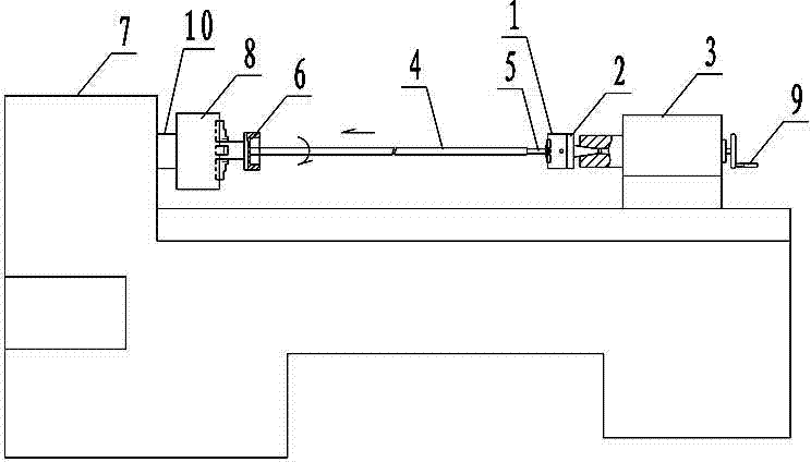
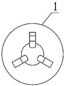
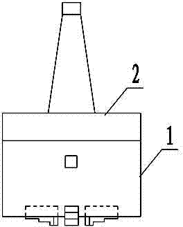
[0014] Such as figure 1 , 2 As shown in 3, the method of using a lathe to process a screw according to the present invention is carried out according to the following steps:

[0015] The first step is to fix the three-jaw chuck 1 on the conical mold handle 2, and install the three-jaw chuck 1 on the tailstock 3 of the lathe through the conical mold handle 2;

[0016] The second step is to turn a truncated cone section 5 at one end of the screw 4 to be processed. The diameter of the truncated cone section 5 is smaller than the diameter of the thread bottom to be processed by 1 mm, and the length of the truncated cone section 5 is twice the thickness of the die + the three-jaw card The clamping length of disc 1;

[0017] The third step is to install the die on the head chuck 8 of the lathe 7 through the die sleeve 6, and the three-jaw chuck 1 on the tailstock 3 of the lathe clamps the circular table section 5 of the screw 4 to be processed. The other end of the screw 4 is chamfered an...


PUM


Abstract

The invention discloses a method for machining a threaded rod through a lathe. The method includes the steps that step 1, a three-jaw chuck is fixed to a cone-shaped die shank; step 2, a section of circular truncated cone is turned at one end of the threaded rod to be machined; step 3, a threading die is installed on a lathe head chuck, the circular truncated cone section of the threaded rod to be machined is clamped through the three-jaw chuck, the other end of the threaded rod to be machined is chamfered and then placed on a mouth of the threading die, the lathe is started, a tailstock hand shank of the lathe is shaken to enable the threaded rod to be machined to enter the threading die, at the moment, under the action of rotation of threading die screw threads, the threaded rod to be machined automatically penetrates through the threading die and enters a hollow main shaft of the lathe, and then the threaded rod machining is completed. The method for machining the threaded rod through the lathe has the advantages of solving the problem that a threaded rod with the diameter smaller than 50mm and the length larger than 1000mm is difficult to machine, according to the method, the maximum machining length of the threaded rod is the lathe bed length of the lathe, the threaded rod is not stressed by radial force in the thread machining process, and therefore precision and smooth finish of the threaded rod machining are greatly improved.

Description

Technical field [0001] The invention relates to a lathe processing method, in particular to a method of using a lathe to process a screw. Background technique [0002] The traditional method of using a lathe to process a screw is to complete the turning process with a threaded turning tool. However, for the processing of a slender screw (with a diameter less than 50mm and a length greater than 1000mm), it is more difficult. The main reason is that the thread turning tool is adjusting The radial force generated in the turning process can easily cause the deformation of the screw, so that the smoothness and accuracy of the screw can not be guaranteed, and the rejection rate is high. Summary of the invention [0003] The object of the present invention is to provide a method for machining a screw using a lathe. [0004] In order to achieve the above objectives, the present invention adopts the following technical solutions: [0005] The method for processing a screw using a lathe accor...

Claims


Application Information

Patent Timeline
Patent Type & Authority Applications(China)
IPC IPC(8): B23G3/08
Inventor 刘秋珍郭永强
Owner ZHENGZHOU JINTAI CANNER
Learn More