
Fish tank bottom filter filtering system

A fish tank and circulation system technology, applied in fish farming, application, animal husbandry, etc., can solve the problems of reducing the viewing area of ​​the fish tank, inconvenient adjustment of the water level of the fish tank, death, etc., and achieve the effect of increasing the viewing area and use volume

Inactive Publication Date: 2014-01-08
夏振宇
View PDF0 Cites 13 Cited by
  • Summary
  • Abstract
  • Description
  • Claims
  • Application Information

AI Technical Summary

Problems solved by technology

The shortcomings of traditional fish tanks are mainly as follows: 1. The reason why traditional fish tanks must use overflow columns is that the water level of the fish tanks is not convenient to adjust. As a result, there is no water or too little water in the bottom filter tank, the water pump is idling and burnt out, and the water circulation is interrupted, making it impossible to purify and filter water, resulting in the decline or even death of aquatic organisms. Frequent adjustment of the water level brings a lot of inconvenience to the breeder. 4 Traditional fish tanks must use overflow columns, which greatly reduces the viewing area of ​​the fish tank and reduces the aesthetics

Method used


Image

  • Fish tank bottom filter filtering system

Examples


Embodiment Construction

[0013] The following descriptions are only preferred embodiments of the present invention, and therefore do not limit the protection scope of the present invention.

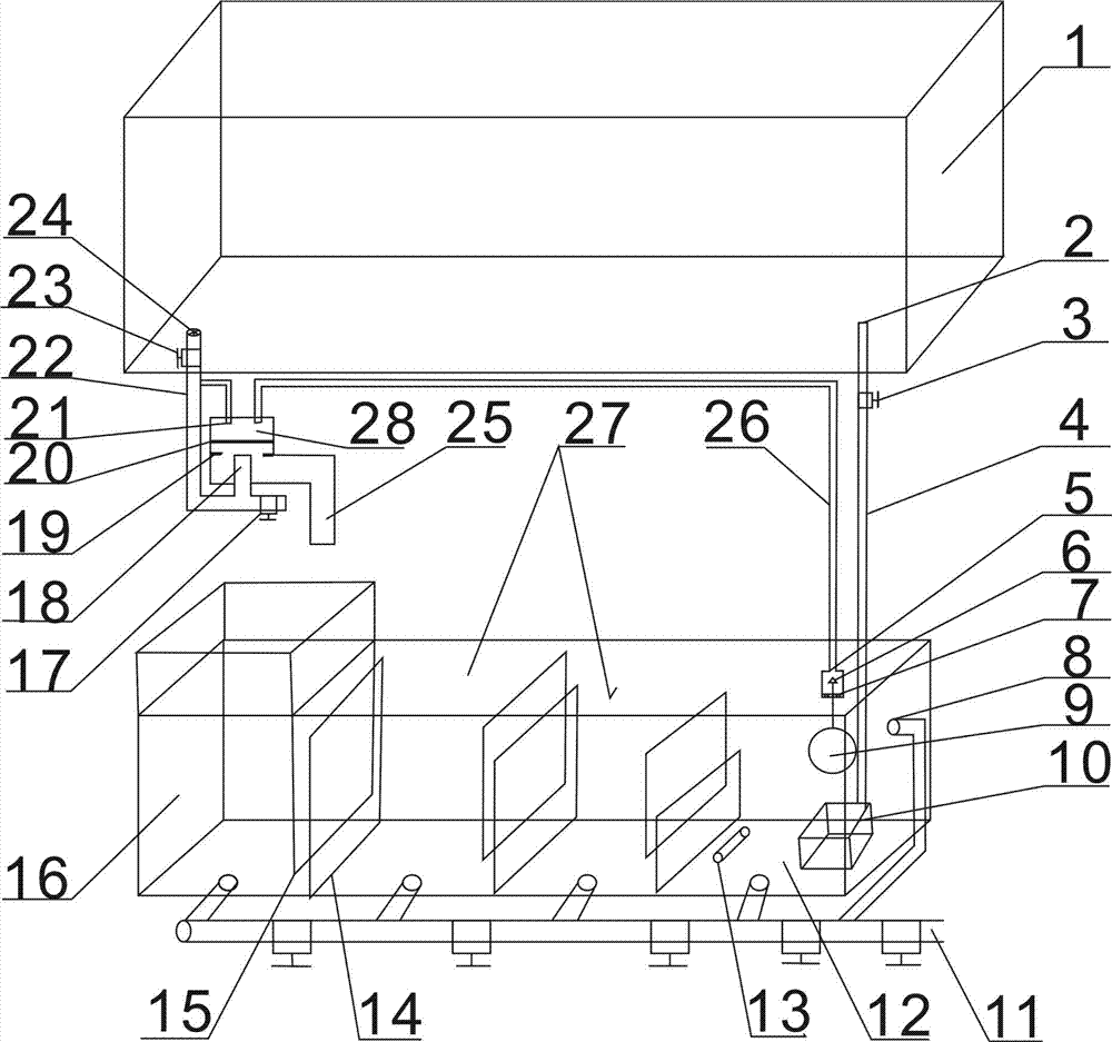
[0014] The fish tank bottom filter filtration circulation system, the water in the fish tank enters the fish tank downpipe 22 through the sieve plate 24, then enters the pressure chamber 28 through the main water inlet pipe 18 of the pressure chamber and enters the bottom filter tank 16 through the main outlet pipe 25 of the pressure chamber. After the water is purified through a series of overflow and filtration in the bottom filter tank, it is finally delivered to the fish tank 1 by the water pump 10 in the water pump chamber 12 (this is the same as most bottom filter tanks on the market, and does not involve patents, so I won’t repeat it).

[0015] When the water level of the water pump chamber 12 reaches a predetermined height, the conical piston 6 is driven by the floating ball 9 to block the outlet pipe 5 ...


PUM


Abstract

The invention provides a fish tank bottom filter filtering system. According to the scheme, overflow plates or overflow columns are not arranged, the water level of a fish tank can be freely adjusted, even if the fish tank is not managed by people for a long time, the phenomena that water circulation is suspended due to dropping of the water level of the fish tank, a water pump is burnt out, and water quality is deteriorated to cause dropping of aquatic life energy and death of aquatic lives can be avoided. In addition, according to the scheme, the water level of a bottom filter tank is stable, a protein separator and other cultivation equipment are convenient to manage, and a large number of workloads of feeders are reduced. Through a designed round gasket 19 and a designed annular gasket 20, the problem of the poor closing effect caused by aging and abrasion of gaskets can be well solved, in a power failure state, due to the fact that a water pump 10 can not convey water of the bottom filter tank 16 into a fish tank 1, the problems that the water level of the fish tank can drop and the water level of the bottom filter tank rises and then water overflows due to the poor closing effect are solved. A valve 17 can discharge water from a main water inlet pipe, water in the fish tank can be conveniently and quickly emptied in necessary, in addition, sand, residues, animal skeletons and other solid-state garbage deposited in the main water inlet pipe can be completely cleaned. A tapered piston 6, a perforated plate 7 and a floating ball 9 are combined to control a water switch of a pressure chamber water outlet pipe 26, and compared with a lever type float valve, the fish tank bottom filter filtering system is firmer and more durable. In addition, the perforated plate 7 can be conveniently demounted, then, solid-state matter accumulated inside the fish tank can be conveniently cleaned, and blockage can be avoided.

Description

technical field [0001] The invention relates to a fish tank accessory system, in particular to a fish tank bottom filter circulation system. Background technique [0002] For the water circulation filtration system of the fish tank, the traditional fish tank water circulation has four main categories: upper filtration, side filtration, bottom filtration, and external filter barrel. The best effect is the bottom filter, but there are still some shortcomings. This design has greatly improved the traditional bottom filter. The shortcomings of traditional fish tanks are mainly as follows: 1. The reason why traditional fish tanks must use overflow columns is that the water level of the fish tanks is not convenient to adjust. As a result, there is no water or too little water in the bottom filter tank, the water pump is idling and burnt out, and the water circulation is interrupted, making it impossible to purify and filter water, resulting in the decline or even death of aquatic...

Claims


Application Information

Patent Timeline
IPC IPC(8): A01K63/04
Inventor 夏振宇
Owner 夏振宇
Learn More