A kind of button structure and its mechanical keyboard and assembly method
A key and key cap technology, applied in electrical components, electrical switches, circuits, etc., can solve the problems of poor sensitivity, high cost, poor keyboard button feel, etc., to reduce welding links, convenient and quick assembly of accessories, and reduce labor costs. Effect
- Summary
- Abstract
- Description
- Claims
- Application Information
AI Technical Summary
Problems solved by technology
Method used
Image

Examples
Embodiment 1
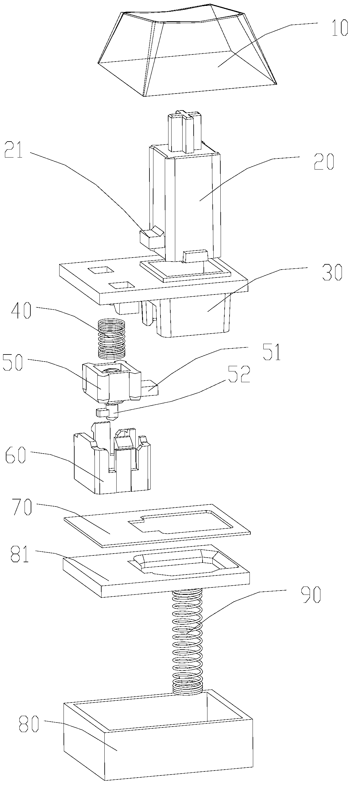
[0034] refer to figure 1 and figure 2 As shown, this embodiment provides a button structure, including a keycap 10, a main shaft 20, an upper cover 30, a main spring 90, a lower cover 80, a conductive film 70, and a secondary shaft 50, wherein the lower cover 80 has a support plate 81, the conductive film 70 is laid on the support plate 81, the support plate 81 and the conductive film 70 of the lower cover 80 and the upper cover 30 are all provided with a through hole through which the main shaft 20 can pass. The through hole of the cover 30 can only pass through the upper half of the main shaft 20. The lower end of the main spring 90 is arranged in the lower cover 80, and the upper part is sleeved in the main shaft 20. The lower surface of the keycap 10 is connected to each other, and a secondary shaft 50 is provided below the opposite end of the through hole provided by the upper cover 30. The secondary shaft 50 is directly connected to the connection point of the conducti...
Embodiment 2
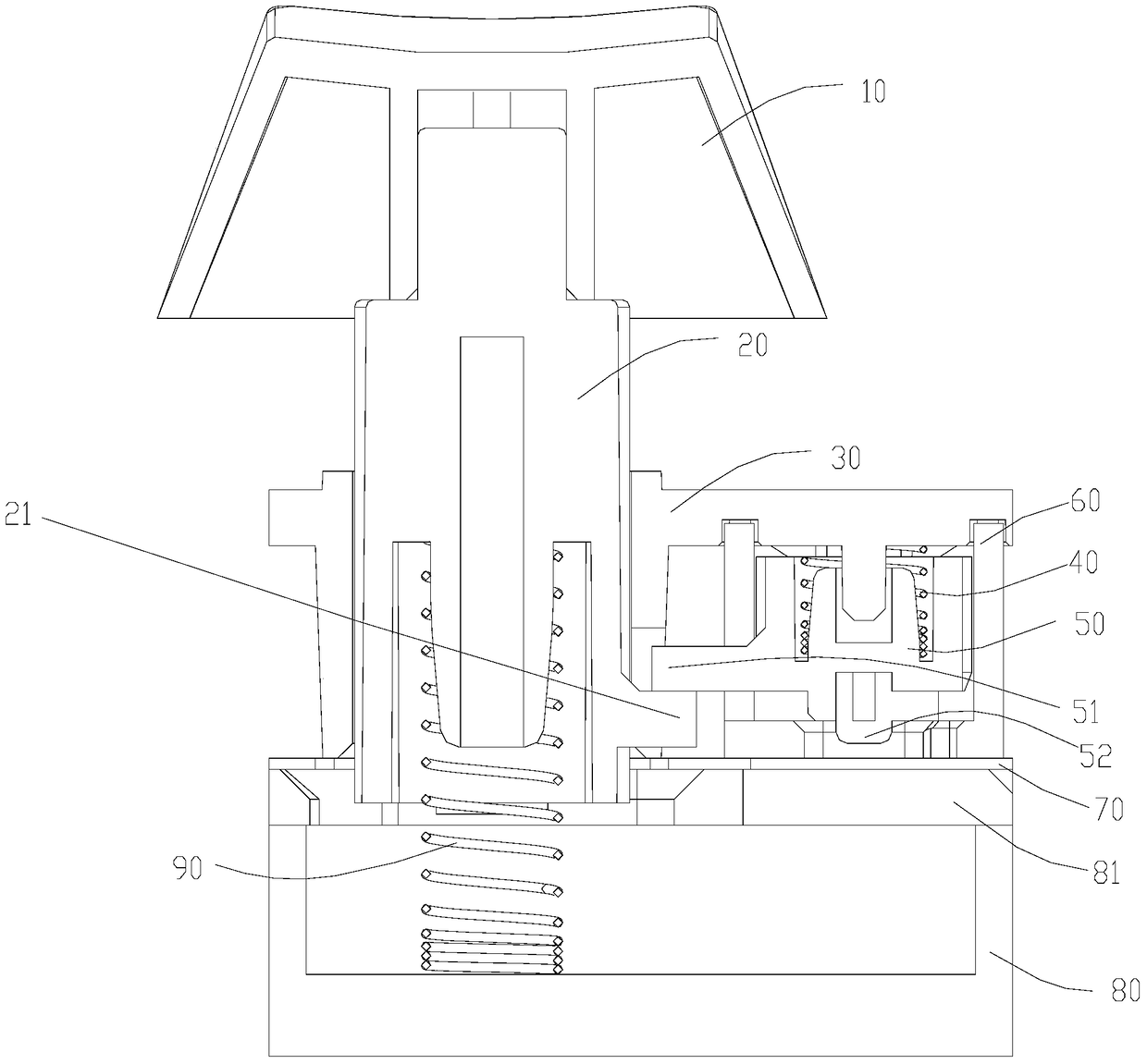
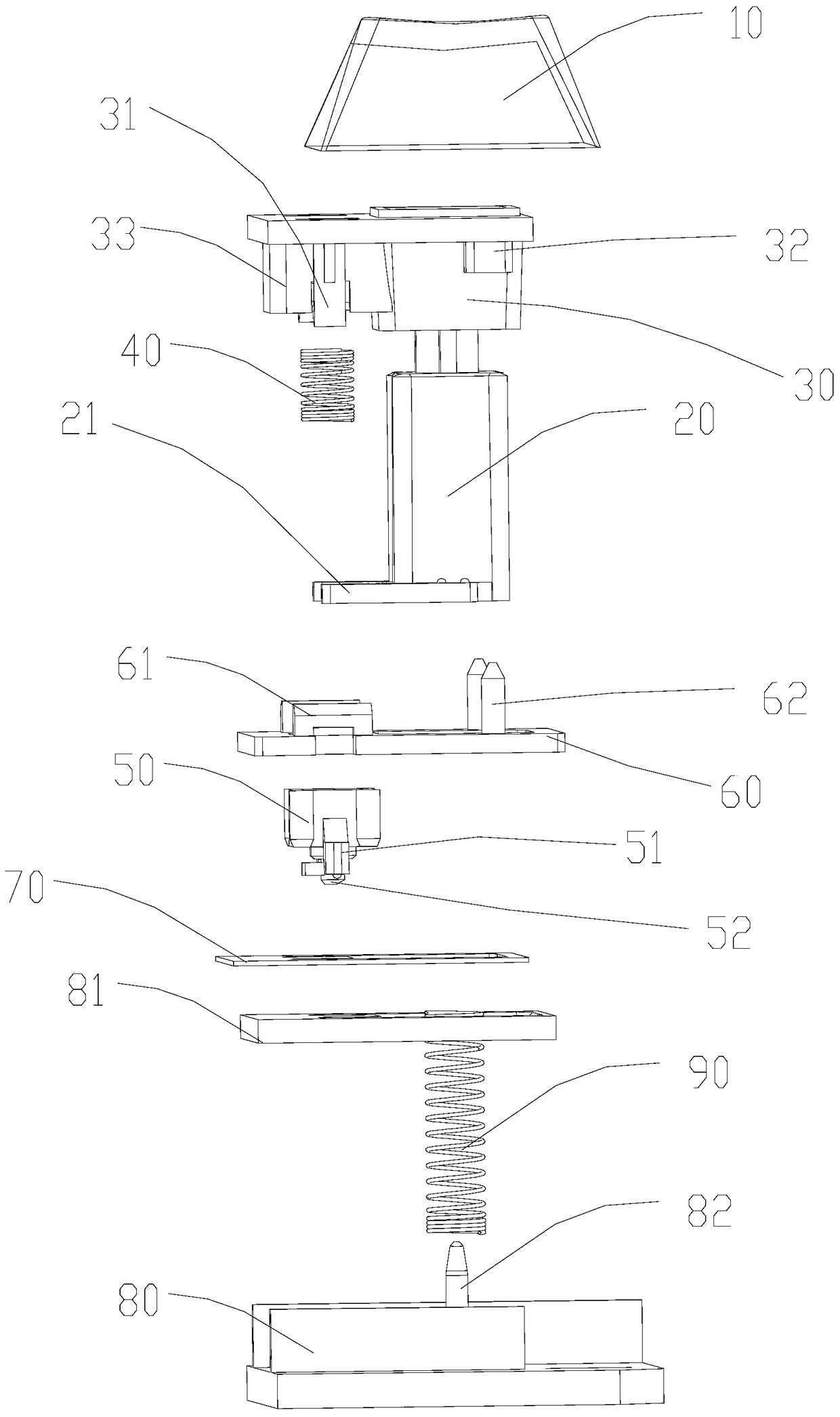
[0037] refer to Figure 3 to Figure 6 As shown, this embodiment provides a button structure, including a keycap 10, a main shaft 20, an upper cover 30, a main spring 90, a lower cover 80, a conductive film 70, and a secondary shaft 50, wherein the lower cover 80 has a A support plate 81 that supports the conductive film 70, the support plate 81 is provided with a through hole that can pass through the lower part of the main shaft 20, and the support plate 81 is fixedly installed on the lower cover 80 , being integrated with it, a conductive film 70 is laid above the support plate 81, and the conductive film 70 and the upper cover 30 are all provided with through holes for the spindle 20 to pass through, and the through holes of the upper cover 30 can only For the upper half of the main shaft 20 to pass through, the lower end of the main spring 90 is set in the lower cover 80, and the upper part is sleeved in the main shaft 20, and the upper part of the main spring 90 is connec...
Embodiment 3
[0045] refer to Figure 3 to Figure 6 As shown, this embodiment provides a method for assembling a mechanical keyboard, using the button structure described in the above-mentioned embodiment 2 and the above-mentioned cover and bottom plate, and the specific assembly steps are as follows:
[0046] Place the upper cover 30 upside down and place it on the working platform, put the secondary spring 40 into the sliding groove 33, and wrap it around the periphery of the second spring fixing ring 34;
[0047] Turn the secondary shaft 50 upside down and put it into the sliding groove 33. The two sides of the secondary shaft 50 have two ears protruding end point bosses 51 located on both sides of the secondary shaft 50, so that the secondary shaft 50 The second fixing column 54 penetrates the auxiliary spring 40 and the second spring fixing ring 34;
[0048] Turn the fixing plate 60 upside down and fasten it on the lower surface of the upper cover 30, use the positioning column 62 to ...
PUM
 Abstract
Description
Claims
Application Information
 - R&D
- Intellectual Property
- Life Sciences
- Materials
- Tech Scout
- Unparalleled Data Quality
- Higher Quality Content
- 60% Fewer Hallucinations
Browse by: Latest US Patents, China's latest patents, Technical Efficacy Thesaurus, Application Domain, Technology Topic, Popular Technical Reports.
© 2025 PatSnap. All rights reserved.Legal|Privacy policy|Modern Slavery Act Transparency Statement|Sitemap|About US| Contact US: help@patsnap.com