
Method used for removing vapour in pyrolysis raw gas, and fixed bed pyrolysis device

A technology of waste gas and water vapor, applied in the field of coal chemical industry

Inactive Publication Date: 2014-01-01
DALIAN UNIV OF TECH
View PDF1 Cites 2 Cited by
  • Summary
  • Abstract
  • Description
  • Claims
  • Application Information

AI Technical Summary

Problems solved by technology

[0005] The object of the present invention is to propose a method for eliminating pyrolysis waste gas in view of the problems of high energy consumption and many equipments in the above-mentioned existing pyrolysis waste gas removal method. The method of water vapor in the coal gas can eliminate the water vapor in the raw coal gas without affecting the tar yield in the raw coal gas, reduce or even remove the pyrolysis water, and then reduce the energy consumption of the coal pyrolysis system

Method used


Image

  • Method used for removing vapour in pyrolysis raw gas, and fixed bed pyrolysis device
  • Method used for removing vapour in pyrolysis raw gas, and fixed bed pyrolysis device
  • Method used for removing vapour in pyrolysis raw gas, and fixed bed pyrolysis device

Examples


Embodiment 1

[0037] This embodiment discloses a fixed bed pyrolysis device, which includes pyrolysis reaction tubes and cold traps the same as the existing fixed bed pyrolysis device, and is different from the existing fixed bed pyrolysis device in this Embodiment The fixed-bed pyrolysis device is also provided with a catalytic reactor for eliminating water vapor in the pyrolysis raw coal gas between the pyrolysis reaction tube and the cold trap. Temperature electric heating device.

Embodiment 2

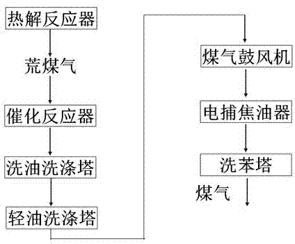
[0039] figure 2 It is the process flow diagram of embodiment 2.

[0040] This embodiment discloses a process flow for pyrolyzing raw gas to eliminate water vapor and recover tar. This process flow is the same as the existing pyrolysis process oil washing process, including a pyrolysis reactor and a washing recovery system. The difference is that in These include catalytic reactors such as figure 2 shown. The raw coal gas produced by the pyrolysis of coal samples is passed into a catalytic reactor equipped with a catalyst. In the catalytic reactor, the water vapor in the raw coal gas and the CO contained in the raw coal gas itself undergo a water-gas shift reaction (CO and water vapor generate The reaction produces CO 2 and hydrogen) to eliminate water vapor, wherein the catalyst is a Co-Mo series sulfur-resistant oil-gas resistant wide-temperature shift catalyst. The raw coal gas after eliminating moisture enters the oil washing tower and light oil washing tower to recov...

Embodiment 3

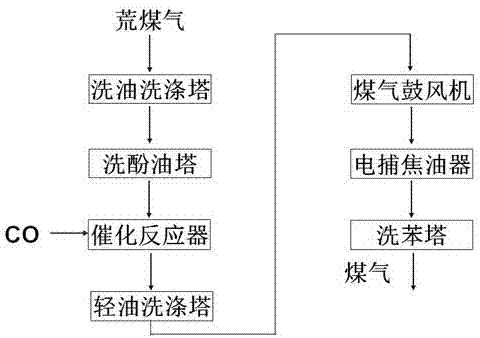
[0042] image 3 It is the process flow diagram of embodiment 3.

[0043] This embodiment discloses a process flow for pyrolyzing raw gas to eliminate water vapor and recover tar. This process flow is the same as the existing pyrolysis process oil washing process, including a pyrolysis reactor and a washing recovery system. The difference is that in These include catalytic reactors such as image 3 shown. The raw coal gas produced by the pyrolysis of coal samples is passed into the oil washing tower and the phenol washing tower to recover part of the tar and phenol oil, and then the raw coal gas containing part of the tar is passed into the catalytic reactor equipped with a catalyst. In the catalytic reactor, The water vapor in the raw coal gas undergoes a water-gas shift reaction with the carrier gas CO to eliminate the water vapor, wherein the catalyst is a Co-Mo series sulfur-resistant, oil-gas and wide-temperature shift catalyst. The raw coal gas after moisture removal e...


PUM

PropertyMeasurementUnit
particle sizeaaaaaaaaaa

Abstract

The invention provides a method used for removing vapour in pyrolysis raw gas, and a fixed bed pyrolysis device. The method used for removing vapour in pyrolysis raw gas comprises following steps: raw gas obtained from pyrolysis of coal samples is delivered into a catalytic reactor filled with a catalyst; and water gas shift reaction of vapour and CO in raw gas is realized in the catalytic reactor so as to remove vapour, wherein the catalyst is a Co-Mo sulfur-tolerant oil-resistant wide-temperature shift catalyst. The invention also provides the fixed bed pyrolysis device used for the method used for removing vapour in pyrolysis raw gas. The steps of the method are scientific and reasonable. The method is capable of removing vapour in pyrolysis raw gas, and reducing and even removing pyrolysis water without influencing tar yield of raw gas so as to reduce energy consumption of coal pyrolysis systems.

Description

technical field [0001] The invention relates to coal chemical technology, in particular to a method for eliminating water vapor in pyrolysis raw coal gas and a fixed bed pyrolysis device. Background technique [0002] A large amount of waste water will be generated in the process of pyrolyzing coal to produce semi-coke, coal tar and gas by low-temperature solid heat carrier method. With the development of coal chemical industry, especially the continuous development and growth of coal pyrolysis industry, the output of wastewater is increasing, and the discharge of a large amount of wastewater has caused serious environmental pollution. Although in coal pyrolysis process design and actual work, various means have been adopted to reduce the generation of wastewater as much as possible, but there is still no effective means to greatly reduce the chemical water generated by the decomposition of organic matter in coal, especially the low-rank coal. chemical water. [0003] At ...

Claims


Application Information

Patent Timeline
Patent Type & Authority Applications(China)
IPC IPC(8): C10K3/04C10B57/00
Inventor 何德民张秋民关珺苗安然
Owner DALIAN UNIV OF TECH
Learn More