Eureka AIR delivers breakthrough ideas for toughest innovation challenges, trusted by R&D personnel around the world.

Battery feeding mechanism of storage battery subsequent unmanned packing device

A technology of feeding mechanism and battery, applied in packaging and other directions, can solve the problems of neglect, heavy battery weight and high price, and achieve the effect of reducing cost, simple mechanism structure and low production and processing cost.

Inactive Publication Date: 2014-01-01
ZHANGJIAGANG ZHIZHOU IND TECH
View PDF0 Cites 0 Cited by
  • Summary
  • Abstract
  • Description
  • Claims
  • Application Information

AI Technical Summary

Problems solved by technology

[0002] In the process of battery processing, after the production of batteries is completed, batches of batteries need to be put into packing boxes, then wrapped with plastic tape, and then tied with packing tape. At present, domestic manufacturers use manual operations to complete the process. , due to the heavy weight of the battery itself, the efficiency is very low, and a lot of manpower is consumed
At present, the domestic battery production industry does not pay much attention to the packaging equipment in the back-end. Most of them are manually operated. The imported foreign production lines include unmanned packaging equipment in the back-end. For battery manufacturers, the cost is high and unacceptable. In recent years, some battery manufacturers have adopted simple mechanical equipment in the last process of bundling cartons. The manual operation still requires a lot of labor. In the latest access requirements of the battery industry, it is clearly stated that the processes involving a large amount of manpower in the production process need to use mechanical automation equipment, and the battery industry will gradually shift from traditional labor-intensive industries to Technology-rich assembly line processing industry

Method used


Image

  • Battery feeding mechanism of storage battery subsequent unmanned packing device
  • Battery feeding mechanism of storage battery subsequent unmanned packing device
  • Battery feeding mechanism of storage battery subsequent unmanned packing device

Examples


Embodiment Construction

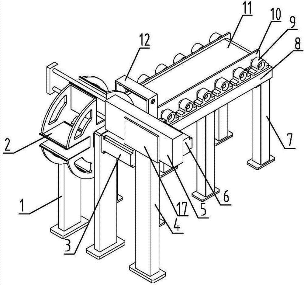
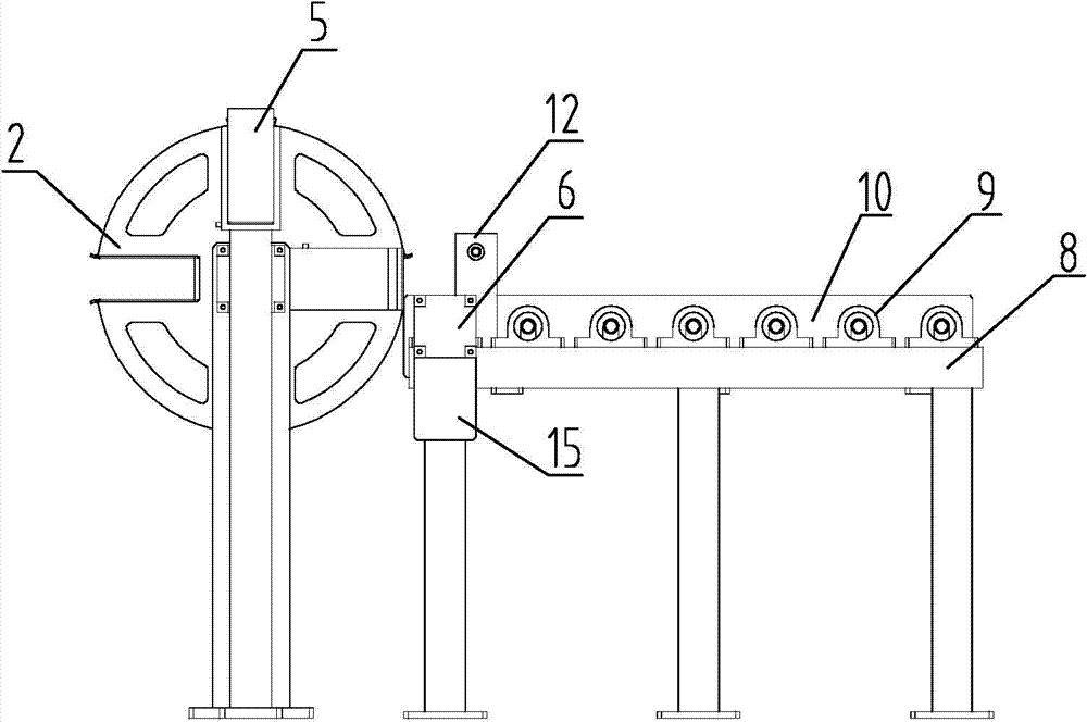
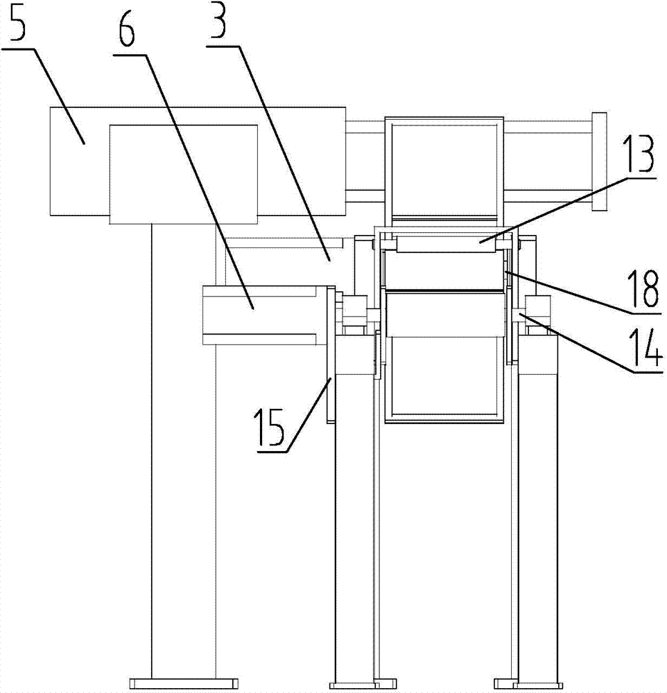
[0013] Such as figure 1 -- Figure 4 As shown, the feeding mechanism of the storage battery rear unmanned packaging equipment in this embodiment includes a biaxial cylinder 5, a cylinder support 17, a servo motor 3, a cylinder column 4, and two distribution trays Column 1, a material distribution tray 2, two baffle plates 10, a rotating main shaft 18, and a belt conveying device, the biaxial cylinder 5 is installed on the cylinder support 17, and the cylinder support is fixed On the cylinder column 4, the rotating main shaft 18 is installed between the two distribution tray columns 1, the described material distribution tray 2 passes through the rotating main shaft 18, and the output shaft of the servo motor 3 is connected to the The rotating main shaft 18 is connected with a shaft coupling, and the material distribution tray 2 is evenly distributed with four gaps. The belt conveying device includes 7 driven roller shafts 16, a main roller shaft 14, and a reduction motor 6. ...


PUM


Abstract

The invention relates to battery processing equipment, particularly to a battery feeding mechanism of a storage battery subsequent unmanned packing device. The mechanism comprises a double-shaft air cylinder, a separating disc, a servo motor, a belt conveying device and a rotation main shaft. The separating disc is uniformly provided with four notches and is controlled by the servo motor to rotate; the push rod of the double-shaft air cylinder is aligned with the vertical notches of the separating disc; the right horizontal notch of the separating disc is aligned with the belt conveying device; the belt conveying device is powered by a reducing motor, and the reducing motor is connected with a driving roller axle through a coupling; the belt conveying device comprises seven driven roller axles, a driving roller axle and a belt, and both sides of the belt are respectively provided with a baffle.

Description

technical field [0001] The invention relates to a battery processing equipment assembly, in particular to a battery feeding mechanism of an unmanned packaging equipment in the rear of a storage battery. Background technique [0002] In the process of battery processing, after the production of batteries is completed, batches of batteries need to be put into packing boxes, then wrapped with plastic tape, and then tied with packing tape. At present, domestic manufacturers use manual operations to complete the process. , due to the heavy weight of the storage battery itself, the efficiency is very low and consumes a lot of manpower. At present, the domestic battery production industry does not pay much attention to the packaging equipment in the back-end. Most of them are manually operated. The imported foreign production lines include unmanned packaging equipment in the back-end. For battery manufacturers, the cost is high and unacceptable. In recent years, some battery manuf...

Claims


Application Information

Patent Timeline
Patent Type & Authority Applications(China)
IPC IPC(8): B65B35/44B65B35/56
Inventor 向伟
Owner ZHANGJIAGANG ZHIZHOU IND TECH
Why Eureka
Eureka Blog
Learn More