Caterpillar track link clamping device

The invention relates to a clamping device and a technology of a chain rail section, which is applied in the field of chain rail section clamping and can solve problems such as processing deformation of the chain rail section.

Inactive Publication Date: 2014-01-01
KUNSHAN KAINUOER METAL PROD
View PDF4 Cites 45 Cited by
  • Summary
  • Abstract
  • Description
  • Claims
  • Application Information

AI Technical Summary

Problems solved by technology

[0003] The object of the present invention is to provide a chain rail link clamping device to solve the problem that the traditional clamping device causes the processing deformation of the chain rail link

Method used


Image

  • Caterpillar track link clamping device

Examples


Embodiment Construction

[0018] The present invention will be further described in detail below in conjunction with the accompanying drawings and embodiments. It should be understood that the specific embodiments described here are only used to explain the present invention, but not to limit the present invention. In addition, it should be noted that, for the convenience of description, only some structures related to the present invention are shown in the drawings but not all structures.

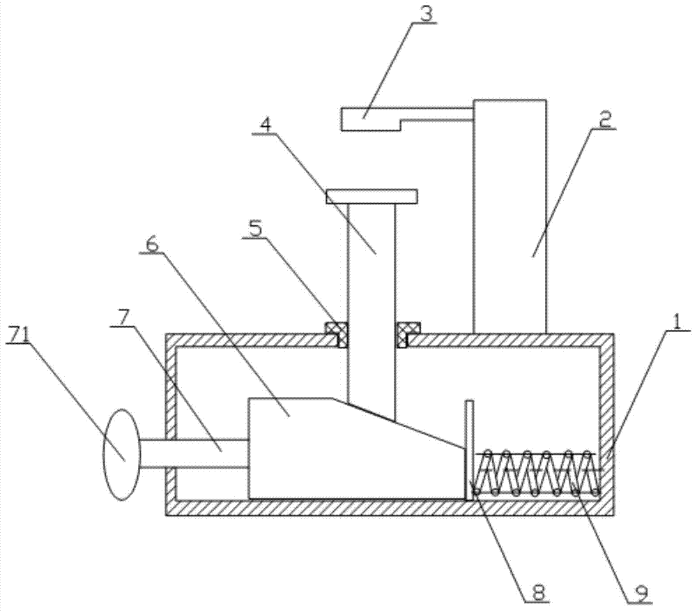
[0019] combine figure 1 The inventive chain rail link clamping device is described in detail.

[0020] The chain rail link clamping device of the present invention includes a main body 1, and also includes a clamping part 4, a flange 5, a wedge block 6 and an adjusting screw 7; the adjusting screw 7 is provided with an external thread and is connected to the external thread through the external thread. The internal thread of the screw hole provided on the side wall of the main body 1 matches, one end of the adjus...


PUM


Abstract

The invention relates to the technical field of caterpillar track link clamping, in particular to a caterpillar track link clamping device. The caterpillar track link clamping device comprises a device body, and further comprises a clamping component, a flange, a wedge block and an adjusting screw, wherein the adjusting screw is provided with an outer thread and is matched with an inner thread of a screw hole formed in the side wall of the device body through the outer thread; one end of the adjusting screw extends into the device body and is connected with the wedge block; an adjusting rotary knob arranged at the other end of the adjusting screw is located outside the device body; the flange is embedded in the upper portion of the device body; the clamping component is arranged in the flange in a penetrating mode, and the lower end of the clamping component is matched with the wedge face of the wedge block. An operator rotates the adjusting screw to move the wedge block, and the wedge block extrudes the clamping component to clamp workpieces; the operator can completely master the clamping process, and caterpillar track links are prevented from deforming when being extruded with overlarge clamping force.

Description

technical field [0001] The invention relates to the technical field of chain rail link clamping, in particular to a chain rail link clamping device. Background technique [0002] At present, the general clamping device used for processing chain rail links adopts the method of directly clamping the workpiece by the oil cylinder, and the clamping force directly acts on the workpiece. Vibration causes processing deformation; if the clamping force of the oil cylinder is too large, the workpiece will be clamped and deformed, which will eventually lead to processing deformation. The above two situations will lead to low machining accuracy or even scrapping of workpieces, resulting in waste and reduced production efficiency. Contents of the invention [0003] The object of the present invention is to provide a chain rail link clamping device, which solves the problem that the traditional clamping device causes the processing deformation of the chain rail link. [0004] For reac...

Claims


Application Information

Patent Timeline
Patent Type & Authority Applications(China)
IPC IPC(8): B23Q3/00
CPCB23Q3/062
Inventor 戎海明
Owner KUNSHAN KAINUOER METAL PROD
Why Eureka
Try Eureka