End cap for a tubular light source

一种光源、管状的技术,应用在管状光源能够安全安装的端帽领域,能够解决安装者暴露等问题,达到低成本的效果

Active Publication Date: 2013-12-25
SIGNIFY HLDG BV
View PDF7 Cites 12 Cited by
  • Summary
  • Abstract
  • Description
  • Claims
  • Application Information

AI Technical Summary

Problems solved by technology

However, since the push-on safety switch according to US 2010 / 018178 may in some cases be inadvertently engaged when the second end of the tubular light source is inserted into the fixture and the installer pushes the first end of the tubular light source, the installed or are exposed to potential hazards (due to unconnected end caps which may then have a live potential)
In addition, the installer may gain a false sense of security because the presence of the safety switch may lead the installer to believe that the installation is safe under all circumstances

Method used


Image

  • End cap for a tubular light source
  • End cap for a tubular light source
  • End cap for a tubular light source

Examples


Embodiment Construction

[0024]The present invention will now be described more fully hereinafter with reference to the accompanying drawings, in which presently preferred embodiments of the invention are shown. However, this invention may be embodied in many different forms and should not be construed as limited to only the embodiments set forth herein; rather, these embodiments are provided for reasons of sufficiency and completeness, and for purposes of presenting this The scope of protection of the invention is fully conveyed to the skilled person. Like reference numerals refer to like elements throughout.

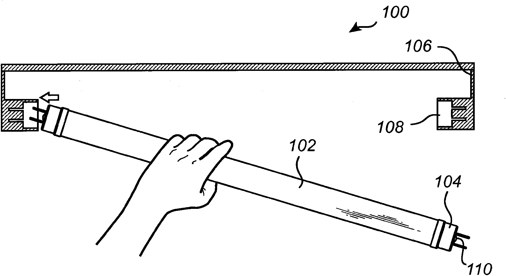
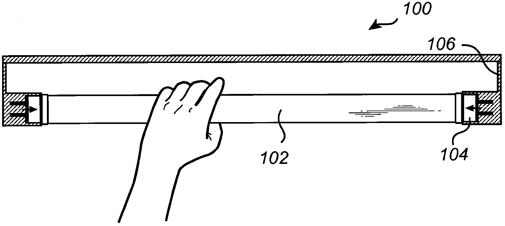
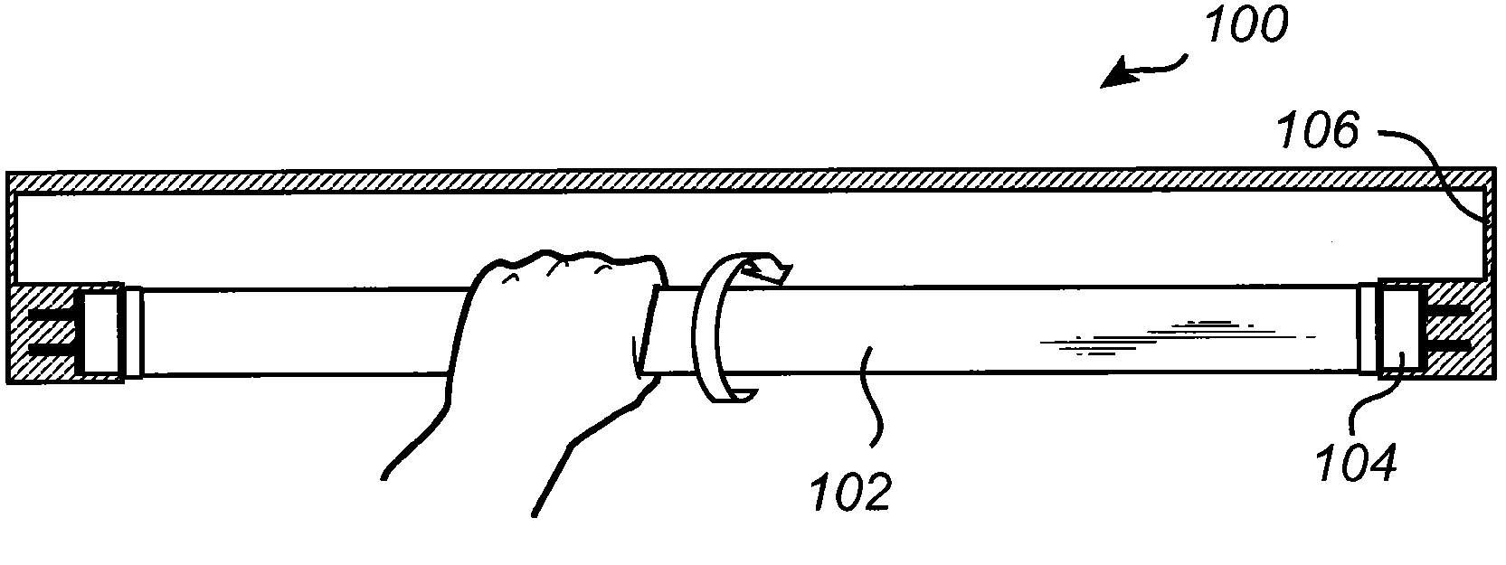
[0025] In the following, various embodiments of end caps according to the invention are discussed with primary reference to the end caps, which provide security to the tubular light source through a two-stage mechanism involving both axial and rotational motion. It should be noted that this in no way limits the scope of protection of the invention, which applies equally to a safety mechanism ...


PUM


Abstract

An end cap (104) for a tubular light source (102), the tubular light source (102) configured to be arranged in a lighting fixture (106) comprising at least one socket (108), wherein the end cap (104) comprises, a first housing portion (202), two connector pins (208) at least partly arranged on an outside of the first housing portion (202) and adapted to fit in the socket (108), and a switch assembly comprising a switch element, wherein the switch assembly being adapted to form a conductive path between the socket (108) and the tubular light source (102) through a depression of the switch element in combination with a relative rotational motion of the first housing portion (202) in relation to the tubular light source (102) as the tubular light source (102) is mounted in the fixture (106).

Description

technical field [0001] The present invention relates to end caps for tubular light sources, and in particular to end caps enabling safe installation of such tubular light sources. Background technique [0002] Due to advantages such as longer service life and higher luminous efficiency compared with incandescent lamps, fluorescent tube lamps are generally used in various lighting systems. However, in a continuing effort to reduce power consumption, it is desirable to replace conventional light tubes with more energy efficient and environmentally friendly alternatives. One such alternative would be to use an LED tube light with multiple LEDs arranged in a tube similar to a daylight tube light. In order to facilitate the transition from fluorescent tube lamps to LED tubular light sources, the LED tubular light sources should be configured to be installed in already existing fixtures for fluorescent tubes. However, the circuitry in an LED tubular light source differs from tha...

Claims


Application Information

Patent Timeline
Patent Type & Authority Applications(China)
IPC IPC(8): F21V23/04F21V19/00H01R33/96H01R13/703H05B41/04F21V23/06F21Y103/00
CPCF21V19/008F21V23/04F21V25/02H01R13/71H01R33/96F21K9/272F21Y2115/10F21K9/27F21V25/00
Inventor M·维霍伊文V·吉伦
Owner SIGNIFY HLDG BV
Why Eureka
Try Eureka