Hall current detection device

A detection device, Hall current technology, applied in the direction of measurement device, voltage/current isolation, measurement of electrical variables, etc., can solve problems such as reducing production efficiency, nonlinearity, and electric shock danger

Pending Publication Date: 2017-11-24
浙江中凯科技股份有限公司
View PDF5 Cites 0 Cited by
  • Summary
  • Abstract
  • Description
  • Claims
  • Application Information

AI Technical Summary

Problems solved by technology

However, the above-mentioned method of using a current transformer with an iron core to detect the current passing through the current-carrying conductor has the following problems: when the current passing through the conductor is large, the magnetic flux generated in the iron core will show nonlinearity, resulting in The change of the mutual inductance coefficient of the transformer reduces the detection accuracy; in addition, due to the limitation of the volume of the iron core itself and the frequency characteristics of the material, the current transformer with the iron core structure cannot detect DC current and higher frequency current, and the detection range is narrow
[0004] Although the Hall current detection device disclosed in the above-mentioned patent document can solve the problems existing in the way of detecting the current passing through the current-carrying conductor by using a current transformer with an iron core, the above-mentioned Hall current detection device uses screws to directly connect the housing. Installed on the current-carrying conductor, in this way, when the Hall current detection device needs to be disassembled and installed, in order to prevent electric shock, it is necessary to stop the work of the equipment connected to the current-carrying conductor, and the current-carrying conductor needs to be in a power-off state, so that all The above shell is disassembled from the current-carrying conductor, and disassembly after power failure will bring a lot of inconvenience. For example, if it is to monitor the current on the production line, when it is necessary to disassemble and install the Hall current detection device, the entire production line will stop working , which greatly reduces production efficiency, affects production, and causes greater losses to the factory; and if the current-carrying conductor is not powered on during the disassembly process, there will be a danger of electric shock, causing harm to the human body, and the safety is poor

Method used


Image

  • Hall current detection device
  • Hall current detection device
  • Hall current detection device

Examples


Embodiment 1

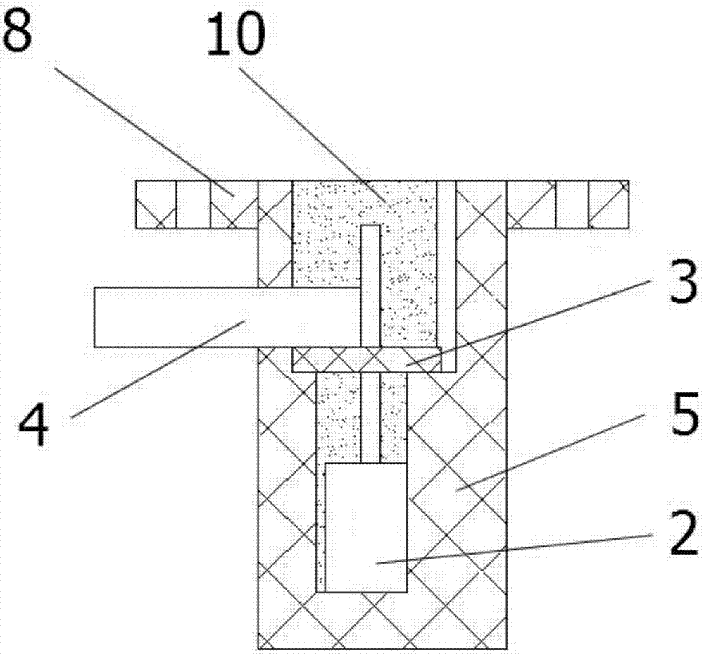
[0046] Such as figure 1 , figure 2 As shown, a Hall current detection device provided in this embodiment includes a current-carrying conductor 1 , an insulating housing structure, a detection assembly and a connecting housing 5 .

[0047] There are various specific forms of the insulating shell structure. In this embodiment, the insulating shell structure includes a first insulating shell 6 and a second insulating shell 7 . The current-carrying conductor 1 is installed on the first insulating shell 6 and is directly and fixedly connected with the first insulating shell 6 ; the second insulating shell 7 is fixedly connected with the first insulating shell 6 . As an alternative embodiment, the insulating case structure may also include only the first insulating case 6 (embodiment 3) or only the second insulating case 7 .

[0048] The detection assembly is used to detect the current passing through the current-carrying conductor 1, and includes a Hall element 2 arranged close ...

Embodiment 2

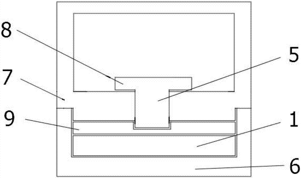
[0057] Such as figure 1 , image 3 As shown, the Hall current detection device provided in this embodiment does not include a controller on the basis of Embodiment 1, and the second insulating casing 7 is another structure indirectly fixedly connected to the current-carrying conductor 1 .

[0058] It should be noted that, in this embodiment, the first insulating shell 6, the second insulating shell 7 and the current-carrying conductor 1 are connected together to form a whole, and the connecting shell 5 is installed on On the second insulating shell 7, it is only necessary to install or disassemble between the connecting shell 5 and the second insulating shell 7, so that the detection assembly can be installed or disassembled without power failure. .

[0059] Refer to Embodiment 1 for the positional relationship between the connection housing 5 and the current-carrying conductor 1. It should be added that in this embodiment, the connection between the current-carrying conduct...

Embodiment 3

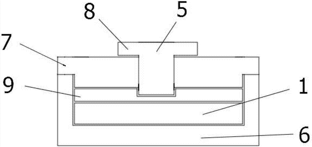
[0062] Such as figure 1 , Figure 4 As shown, the present embodiment provides a Hall current detection device. On the basis of Embodiment 1, the insulating housing structure only includes the first insulating housing 6 and does not include the second insulating housing 7. The connecting shell 5 is detachably fixedly installed with the first insulating shell 6 .

[0063] It should be noted that, in this embodiment, by directly installing the connecting shell 5 on the first insulating shell 6, it is only necessary to carry out the connection between the connecting shell 5 and the first insulating shell 6. Installing or dismounting means that the detection components can be installed or disassembled even when the power supply is not interrupted. . The place where the current-carrying conductor 1 is close to the Hall element 2 can be arranged in a convex, flat or concave shape, so that a certain distance can be achieved between the current-carrying conductor 1 and the Hall elem...


PUM


Abstract

The invention provides a Hall current detection device, comprising a current-carrying conductor, an insulated shell structure, a detection assembly and a connecting shell, wherein the insulated shell structure is directly or indirectly fixedly connected with the current-carrying conductor; the detection assembly is used for detecting current flowing through the current-carrying conductor, and comprises a Hall element close to the current-carrying conductor, a circuit board electrically connected with the Hall element and an output lead electrically connected with the circuit board; and the connecting shell is an insulated shell, fixedly connected with the Hall element, and detachably fixedly mounted with the insulated shell structure. The technical problem to be solved by the invention is to overcome the defects that the Hall current detection device in the prior art, which needs to be disassembled and assembled in a power-off manner, lowers the production efficiency, affects the production and has low safety, thus providing a Hall current detection device which is disassembled and assembled with power, does not lower the production efficiency, does not affect the production and has high safety.

Description

technical field [0001] The invention relates to the technical field of electrician detection, in particular to a Hall current detection device. Background technique [0002] In the technical field of electrical testing, a current transformer with an iron core is usually used to detect the current passing through a current-carrying conductor. The traditional current transformer mainly includes three parts: iron core, primary winding and secondary winding. The basic working principle of the current transformer is to convert the large current on the secondary side into a small current on the primary side according to the principle of electromagnetic induction and then measure it. . However, the above-mentioned method of using a current transformer with an iron core to detect the current passing through the current-carrying conductor has the following problems: when the current passing through the conductor is large, the magnetic flux generated in the iron core will show nonlin...

Claims


Application Information

Patent Timeline
IPC IPC(8): G01R15/20
CPCG01R15/202
Inventor 黄世泽杨阳穆茂林朱谅屠瑜权屠旭慰田新疆欧阳东
Owner 浙江中凯科技股份有限公司
Why Eureka
Try Eureka