Electrical box and sleeve assembly

a technology of electrical boxes and sleeves, applied in the direction of electrical devices, etc., can solve the problems of time-consuming and labor-intensive, difficulty in accurately locating a template to meet this need, and high cost, and achieve the effect of convenient removal

Inactive Publication Date: 2016-08-04
BRAINWAVE RES CORP
View PDF0 Cites 9 Cited by
  • Summary
  • Abstract
  • Description
  • Claims
  • Application Information

AI Technical Summary

Benefits of technology

The patent text describes a device that is inserted into a sleeve and held in place using a spring latch. The device has a connector for wiring and can be easily removed. The sleeve flange can be engaged with a coverplate for easy installation. The device can also have multiple wiring contacts or ports for connecting to the wires of the box. The technical effects of this design include easy installation, protection of electrical components, and safety compliance.

Problems solved by technology

Cutting an opening in the wall substrate that is appropriately sized and placed can be time consuming.
Difficulties exist in accurately locating a template to meet this need.
The conventional procedures for installation of electrical boxes and formation of substrate openings therefore thus involve a considerable expenditure of time and effort.

Method used


Image

  • Electrical box and sleeve assembly
  • Electrical box and sleeve assembly
  • Electrical box and sleeve assembly

Examples


Embodiment Construction

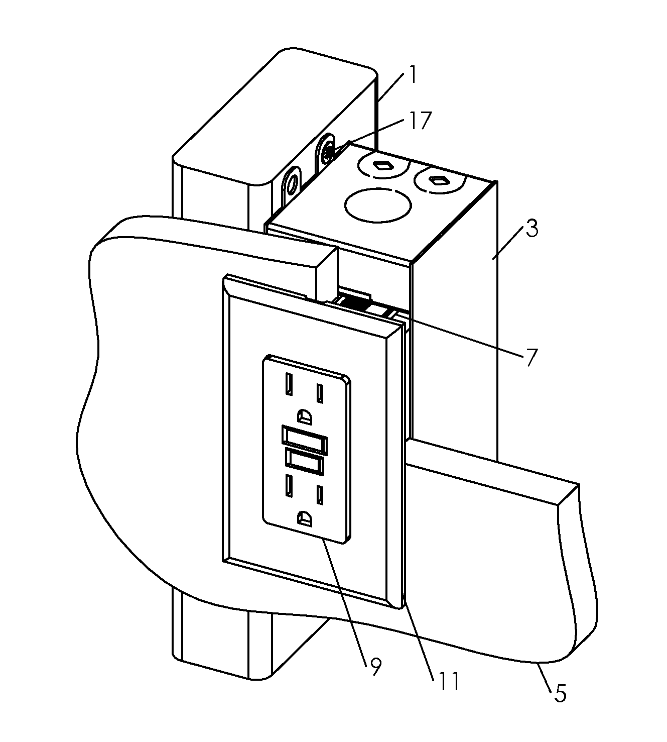
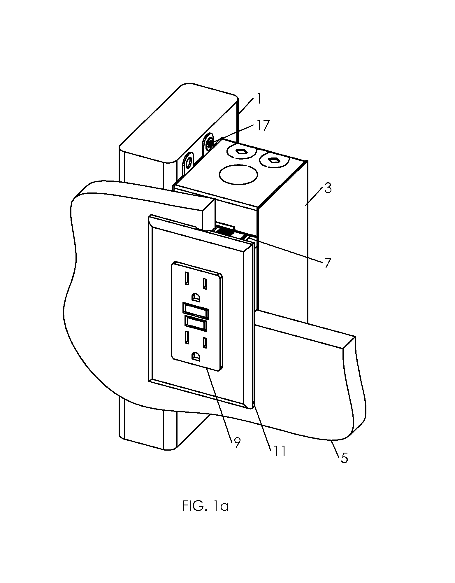
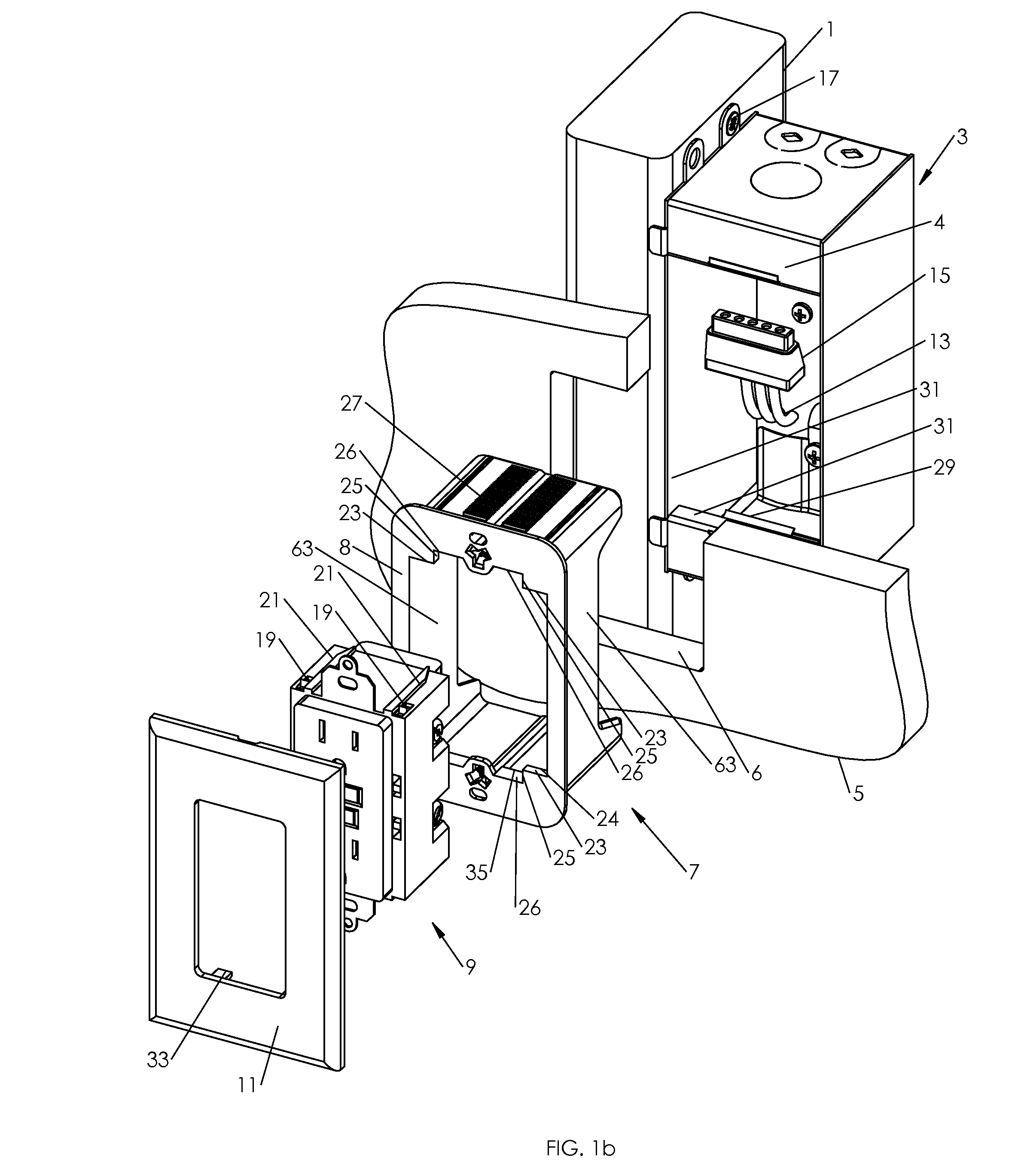
[0086]FIGS. 1a-e show electrical box 3 mounted on stud 1 with fasteners 17. Drywall 5 is mounted on the studs 1. Hole 6 in drywall 5 or other wall substrate may be cut using a rotating cutting tool with a guide point running along box front inside perimeter wall 31 disclosed in U.S. patent application Ser. No. 13 / 690,849, filed Nov. 30, 2012. Sleeve 7 can be pushed through hole 6 in drywall 5 into box 3 until sleeve flange 8 contacts the front surface of drywall 5 or other wall substrate with any thickness such as, for example between one quarter inch to one and one quarter inch or greater. Sleeve 7 with perimeter wall, or flange surface, 63 serves to completely enclose the line voltage volume of the installation through the thickness of drywall 5 as is typically required by the electrical code regardless of whatever drywall 5 and cladding may be installed later. Sleeve 7 thus replaces the need to install a conventional electrical box proud of stud 1 by the thickness of drywall and ...


PUM


Abstract

An assembly includes a box and a removable sleeve that is engageble with the box and with a wall substrate to secure tight contact between the wall substrate and the box structure, irrespective of the thickness of the wall substrate. The sleeve is configured to be coupled to an electrical device having a corresponding configuration for insertion in the box.

Description

[0001]This application is a Divisional of U.S. application Ser. No. 13 / 745,034, filed Jan. 18, 2013, which is a provisional application 61 / 587,957, filed Jan. 18, 2012 on behalf of inventors Jean-Guy Gagne and James Rogers, is claimed under 35 U.S.C. 119(e).BACKGROUND[0002]This disclosure is related to installation of electrical components in building walls, more particularly, to installation of support structure for line voltage and low voltage devices and the like. Existing electrical codes require containment of electrical switches and receptacles within electrical boxes. In new house or building construction, line current electrical boxes typically are attached to wall studs or joists before drywall or equivalent sheet material is applied to enclose the wall space. An opening is cut in the sheet material to accommodate the box or boxes that have been mounted in known positions. According to code, the enclosure of a line voltage electrical device must be in continuity with the wa...

Claims


Application Information

Patent Timeline
Patent Type & Authority Applications(United States)
IPC IPC(8): H02G3/12H02G3/08
CPCH02G3/12H02G3/083H02G3/086H02G3/123H02G3/14
Inventor GAGNE, JEAN-GUYROGERS, JAMES W.
Owner BRAINWAVE RES CORP
Why Eureka
Try Eureka