
Anchor rod engineering stress simulation experimental device

A technology for simulating experimental devices and bolts, applied in the direction of applying stable tension/pressure to test the strength of materials, etc., which can solve problems such as complex interaction relationships, failure to reflect the stress state of the bolt, and difficulty in simulating the stress of the bolt , to achieve the effect of low test cost and simple structure

Inactive Publication Date: 2013-12-25
SHANDONG UNIV OF SCI & TECH
View PDF5 Cites 3 Cited by
  • Summary
  • Abstract
  • Description
  • Claims
  • Application Information

AI Technical Summary

Problems solved by technology

[0005] However, due to the complex interaction between the anchor and the surrounding rock, it is generally difficult to simulate the force of the anchor at the engineering site in the laboratory
In the existing laboratory tests, the traditional pull-out test is generally used to test the anchor rod. During the test, the exposed end of the anchor rod bears the tensile force, so that the anchor rod is pulled out from the matrix; however, the anchor rod is used in the actual tunnel engineering In the middle, there is no other external pull-out force except for a part of the pre-stressed force applied in advance, and the above-mentioned surrounding rock deformation is the most fundamental cause of the force on the bolt
Because the stress state of the anchor rod under the pull-out test conditions is very different from the stress state under the field conditions, the conventional pull-out test cannot reflect the stress state of the anchor rod under the field conditions.

Method used


Image

  • Anchor rod engineering stress simulation experimental device
  • Anchor rod engineering stress simulation experimental device
  • Anchor rod engineering stress simulation experimental device

Examples


Embodiment Construction

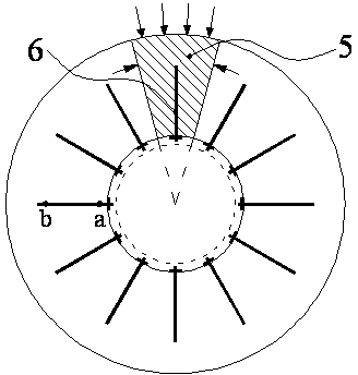
[0027] combined with figure 1 , the principle of using local test pieces in the present invention is that the stress, deformation and damage of the tunnel surrounding rock can be approximately regarded as an axisymmetric problem, therefore, a part of it can be taken, that is, the trapezoidal test piece 5 and the anchor rod described in the present invention Test piece 6 can reflect the properties of the surrounding rock as a whole. Compared with the full-section experimental device, the present invention can carry out large-scale experimental research.

[0028] combined with figure 2 and 3 , a force simulation experiment device for bolt engineering, comprising a U-shaped groove 1, a triangular prism pad 2, a loading pad 3, a side baffle 4, a trapezoidal test piece 5 and a bolt test piece 6.

[0029] The U-shaped groove 1 is an integral structure, including a bottom plate and two side walls, and the lower surface of the bottom plate is in contact with the loading device of t...


PUM


Abstract

The invention discloses an anchor rod engineering stress simulation experimental device. The anchor rod engineering stress simulation experimental device comprises a U-shaped groove, a triangular prism cushion block, a loading cushion block, side baffles, an approximately trapezoidal test piece and anchor rod test pieces. The anchor rod engineering stress simulation experimental device can be used for simulating the stress state of an anchor rod in an engineering field, and truly reflecting the interaction process between a surrounding rock and the anchor rod in tunnel engineering to obtain a true stress distribution curve of the anchor rod, so that the anchor rod engineering stress simulation experimental device has great significance on the research on the properties of stress, deformation, damage and the like of a deep high stress anchored rock mass. According to the anchor rod engineering stress simulation experimental device, part of a deeply buried circular tunnel surrounding rock is subjected to analysis, so that compared with an existing whole sectional model test device, large-scale model tests can be carried out, and the test results are closer to those of the anchor rod in the practical application.

Description

technical field [0001] The invention relates to the research on the force law of anchor rods used in the field of geotechnical engineering at the engineering site, in particular to a force simulation experiment device for anchor rod engineering. Background technique [0002] As an effective support method, bolts have been widely used in various fields of underground engineering such as coal mine roadways, mountain tunnels and urban subways. However, due to the complexity of the interaction between the anchor and the surrounding rock, the distribution of the axial force and the interface shear stress of the anchor is still unclear, and it is difficult to accurately quantitatively evaluate its support effect in engineering practice. Design still faces challenges. [0003] Such as figure 1 As shown in , after the excavation of the underground tunnel, under the stress of the original rock, the inner surface of the surrounding rock converges and deforms to the position indicate...

Claims


Application Information

Patent Timeline
IPC IPC(8): G01N3/08
Inventor 王刚吴学震蒋宇静孙红松
Owner SHANDONG UNIV OF SCI & TECH
Learn More