
Method for regulating indoor temperature and dual-temperature control valve

A technology of indoor temperature and adjustment method, applied in heating and ventilation control systems, heating methods, household heating, etc., can solve problems affecting indoor environment comfort and other problems, achieve low power consumption, reduce product costs, and reduce installation and wiring. Effect

Active Publication Date: 2013-12-25
陈建平
View PDF5 Cites 15 Cited by
  • Summary
  • Abstract
  • Description
  • Claims
  • Application Information

AI Technical Summary

Problems solved by technology

[0009] The first technical problem to be solved in the present invention is: to overcome the existing indoor temperature cascade adjustment method in summer through cold water cooling and dehumidification, when the indoor heat load is low but the humidity load is not low, that is, the heat and humidity are relatively small, resulting in Indoor relative humidity is relatively high, which affects the comfort of the indoor environment. Provide an indoor temperature adjustment method that can take into account cooling and dehumidification in summer and fully reduce the power consumption of water pumps in winter.

Method used


Image

  • Method for regulating indoor temperature and dual-temperature control valve
  • Method for regulating indoor temperature and dual-temperature control valve
  • Method for regulating indoor temperature and dual-temperature control valve

Examples


Embodiment Construction

[0044] The present invention will be described in further detail below in conjunction with the accompanying drawings.

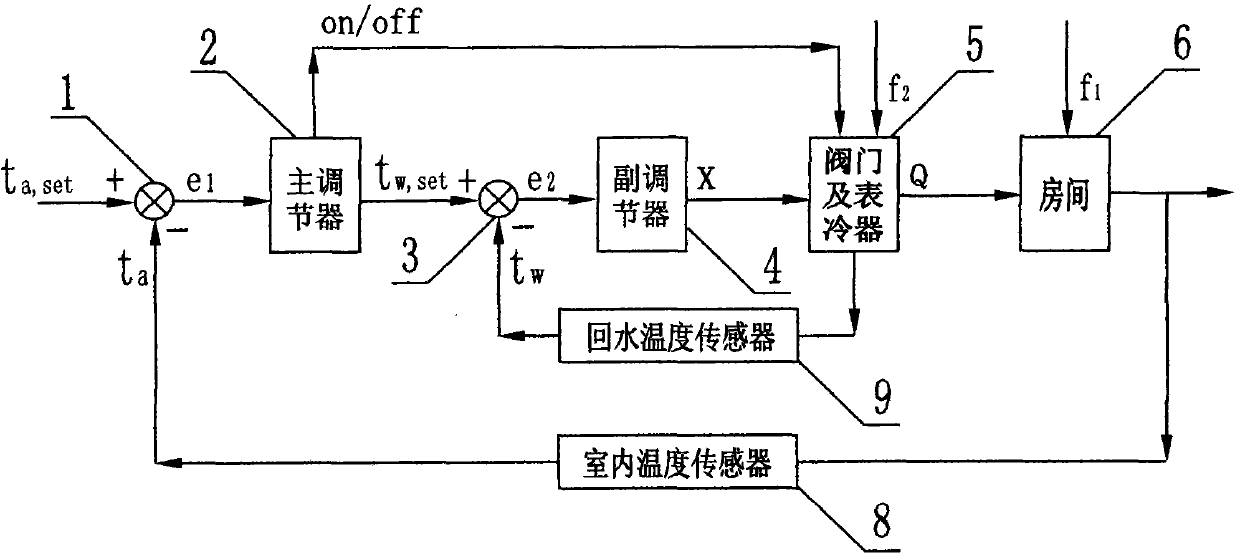
[0045] figure 1 It is a schematic diagram of the indoor temperature cascade adjustment system currently used in the air conditioning system. The cascade adjustment system uses the main regulator 2 and the sub-regulator 4, and the two regulators are connected in series. The output of the main regulator 2 is used as the sub-regulator Given by the controller 4, the output of the sub-regulator 4 is sent to the valve and the surface cooler 5; the supply air temperature ts is introduced as a secondary variable to stabilize the main variable indoor temperature ta; the whole system includes two control loops, the main loop and the secondary loop , the main circuit consists of comparison element 1 (a part of the main regulator 2), the main regulator 2, the comparison element 3 (a part of the sub-regulator 4), the sub-regulator 4, the valve and the surface cooler 5, th...


PUM


Abstract

The invention relates to a method for regulating the indoor temperature and a dual-temperature control valve for implementing the method. The method is used for regulating the indoor temperature of an air conditioning system in a cascade manner by means of cooling and dehumidifying indoor air by the aid of cold water in summers and heating the indoor air by the aid of hot water in winters, and the dual-temperature control valve is used for implementing the method. The method and the dual-temperature control valve have the advantages that an indoor temperature cascade regulation system comprises two regulators which are serially connected with each other to work, and the temperature of supplied air or the temperature of return water is used as an auxiliary variable, so that the indoor temperature which is a main variable can be stabilized; the auxiliary variable has a largest limiting value when refrigerating and dehumidifying requirements need to be met simultaneously in summers, regulating valves are switched off when the indoor temperature is close or equal to a given value, accordingly, the indoor humidity can be taken into consideration while the requirement on the indoor temperature is met, the refrigerating capacity of the cold water is saved, the comfortableness of an indoor environment can be guaranteed, a water flow rate and the overshoot further can be reduced, the transition time can be shortened, dynamic characteristics of procedures can be improved, particularly, secondary disturbance resistance such as water-temperature resistance and water-pressure-variation resistance can be greatly improved, and purposes of further improving the regulation quality of the system, reducing power consumption of water pumps and improving the efficiency of a main unit can be achieved.

Description

technical field [0001] The present invention relates to an indoor temperature adjustment method and a dual temperature control valve using the method, in particular to an indoor temperature cascade adjustment method for an air-conditioning system in which indoor air is cooled and dehumidified by cold water in summer and heated by hot water in winter, and the method is applied. Dual temperature control valves. Background technique [0002] Indoor air is cooled and dehumidified by cold water in summer and heated by hot water in winter. The indoor temperature adjustment of the air conditioning system often adopts a simple single-loop adjustment system, that is, the output signal controls the regulating valve according to the deviation between the indoor temperature and the given value to achieve indoor temperature. Regulation, but the regulation quality of the indoor temperature single-loop regulation system is not good, the adaptability to the regulation object and load change...

Claims


Application Information

Patent Timeline
IPC IPC(8): F24F11/00F24F11/02
Inventor 陈建平
Owner 陈建平
Learn More