A swing mechanism and concrete pumping equipment

A technology for concrete pumps and equipment, which is applied in the direction of mechanical equipment, pumps, building structures, etc., to achieve the effect of increasing the swing speed, increasing the oil output, and reducing the extension speed

Active Publication Date: 2017-04-05
SANY AUTOMOBILE MFG CO LTD
View PDF9 Cites 5 Cited by
  • Summary
  • Abstract
  • Description
  • Claims
  • Application Information

AI Technical Summary

Problems solved by technology

[0004] In view of this, the present invention proposes a swing mechanism and concrete pumping equipment to solve the problem of the swing speed of the swing mechanism and the reversing time of the concrete pumping equipment

Method used


Image

  • A swing mechanism and concrete pumping equipment
  • A swing mechanism and concrete pumping equipment
  • A swing mechanism and concrete pumping equipment

Examples


Embodiment Construction

[0024] It should be noted that, in the case of no conflict, the embodiments of the present invention and the features in the embodiments can be combined with each other. The present invention will be described in detail below with reference to the accompanying drawings and examples.

[0025] Combine below Figure 2 to Figure 4 , the preferred embodiment of the present invention will be described in further detail, and the rocking mechanism of this preferred embodiment is taken as an example:

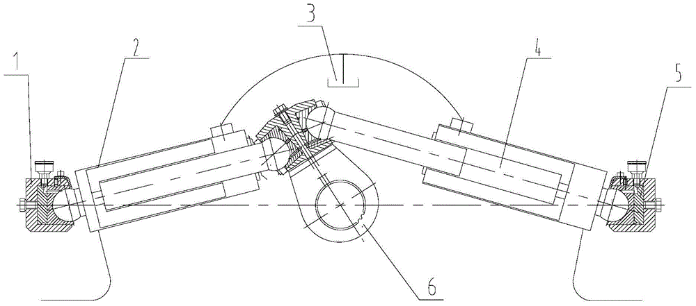
[0026] Such as figure 2 As shown, a swing mechanism is used to drive the distribution valve of the concrete pumping equipment to swing, including a swing arm 6 for driving the distribution valve, two hydraulic cylinders for driving the swing arm 6 to swing left and right, and the left hydraulic cylinder 22 The swing arm 6 is driven to swing to the right, and the right side hydraulic cylinder 4 drives the swing arm 6 to swing to the left. The cylinder barrel 10 of the left hydraulic c...


PUM


Abstract

A wobbler mechanism is used for driving a distributing valve of a concrete pumping device to wobble, and comprises a wobbling arm (6) for driving the distributing valve, and two hydraulic oil cylinders (2, 4) for driving the wobbling arm (6) to wobble from side to side. One end of each of the two hydraulic oil cylinders (2, 4) is connected to left and right sides of the wobbling arm (6), and the hydraulic oil cylinders (2, 4) are two-stage hydraulic oil cylinders (2, 4). Also disclosed is a concrete pumping device having the wobbling mechanism. The wobbling mechanism and the concrete pumping device having the wobbling mechanism is fast in direction change and has a low impact, so that the direction change time of the wobbling mechanism is close to that of a master cylinder of the concrete pumping device, thereby greatly improving pumping continuity.

Description

technical field [0001] The invention relates to the field of engineering machinery, in particular to a rocking mechanism of concrete pumping equipment and the concrete pumping equipment. Background technique [0002] Such as figure 1 As shown: the pumping mechanism of the existing concrete pump includes: main oil cylinders 1a, 1b, water tank 2, delivery cylinders 3a, 3b, concrete pistons 4a, 4b, swing mechanism, mixing system 6, hopper 7 and distribution valve 8 and other main components. Swing mechanism is made up of left and right two swing valve oil cylinders 5a, 5b and swing arm. In the pumping state, under the action of the main cylinders 1a and 1b, the concrete piston 4b advances and 4a retreats. At this time, the swing valve cylinder 5b of the swing mechanism is in the extended state, and 5a is in the backward state. The swing arm drives the distribution valve 8 to swing , the distribution valve 8 is connected to the concrete delivery cylinder 3b, and the concrete ...

Claims


Application Information

Patent Timeline
Patent Type & Authority Patents(China)
IPC IPC(8): F15B11/16F15B15/06F15B15/17E04G21/04
CPCF15B15/061F04B15/02
Inventor 胡任黄勃康磊
Owner SANY AUTOMOBILE MFG CO LTD
Why Eureka
Try Eureka