
Intermeshing element mixer

A technology of mixers and mixing parts, which is applied in the field of raw material extrusion machines, can solve the problems of inability to remodel, increase the cost of mixers, and complicate CTM installation, and achieve the effect of less cost and shorter overall length

Inactive Publication Date: 2008-10-08
RAUWENDAAL EXTRUSION ENG
View PDF1 Cites 0 Cited by
  • Summary
  • Abstract
  • Description
  • Claims
  • Application Information

AI Technical Summary

Problems solved by technology

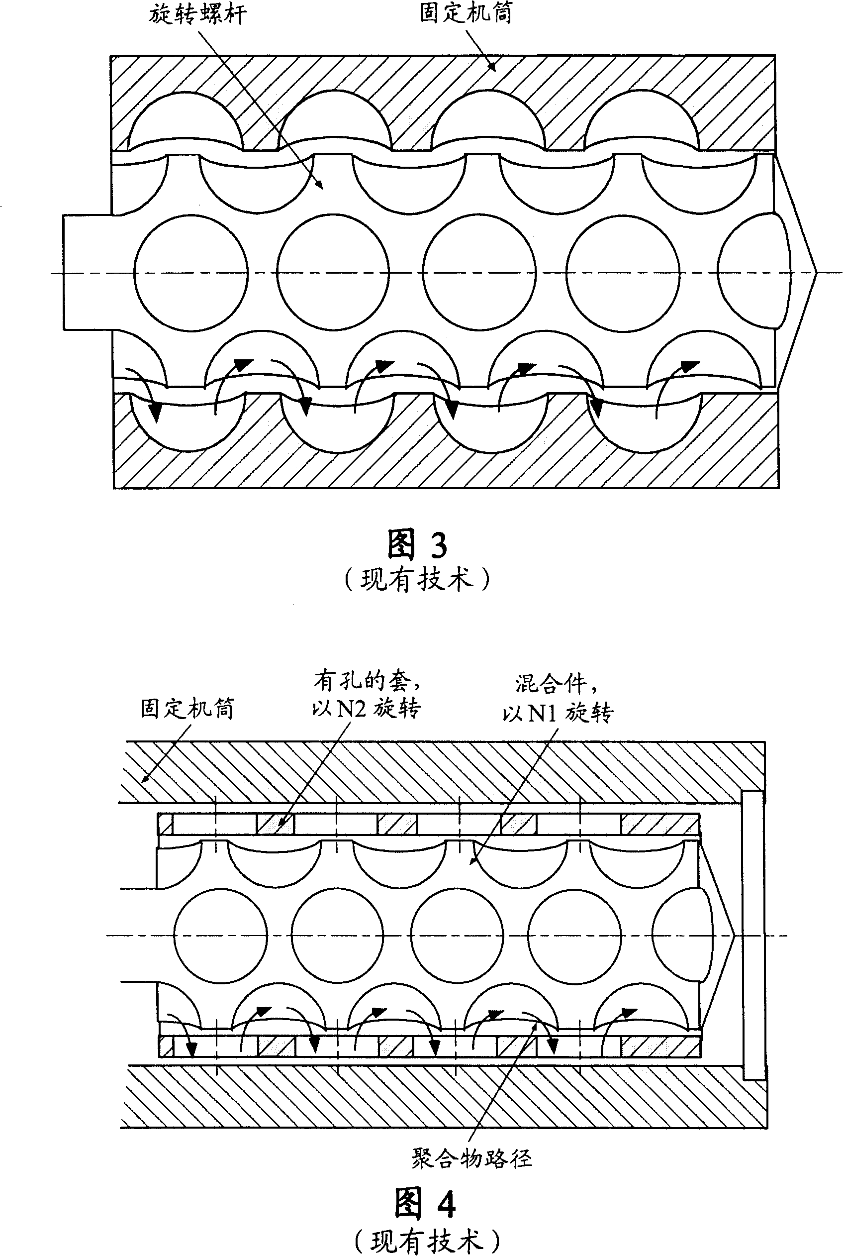
This means that an additional CTM barrel must be installed, which greatly increases the cost of the mixer and complicates the installation of the CTM
[0014] 3. The surface of the barrel is no longer completely wiped by the screw
The hollow outer shaft is driven by gears, obviously it cannot be retrofitted in conventional screw extruders or plasticizing units

Method used


Image

  • Intermeshing element mixer
  • Intermeshing element mixer
  • Intermeshing element mixer

Examples


Embodiment Construction

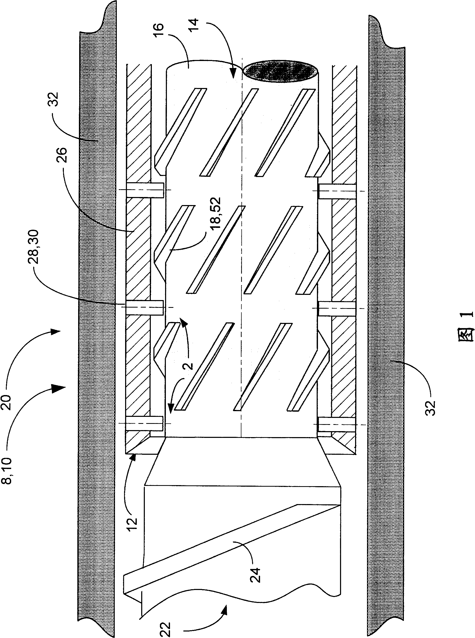
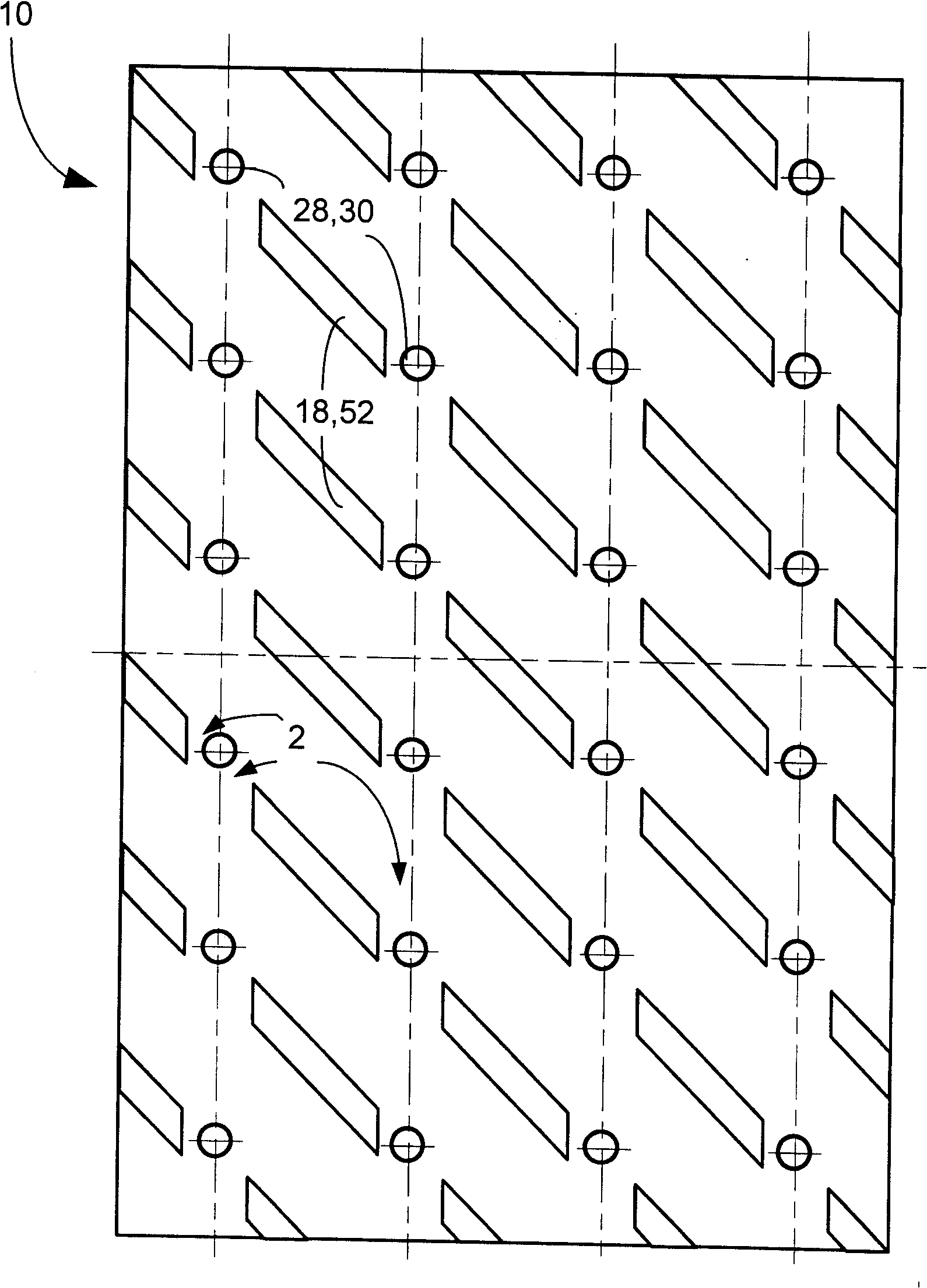
[0051] Objects and advantages of the present invention will become apparent from the following detailed description taken in conjunction with the accompanying drawings, in which FIG. 1 shows a mixer 10 of the present invention, used in the manner of a screw extruder 8 . In the screw extruder 8 , a central screw 14 comprises a central shaft 16 with a plurality of protruding mixing elements 18 arranged in a mixing section 20 . It should be understood that the screw 14 may preferably have additional portions thereon that are primarily concerned with conveying the material, one such conveying portion 22 shown having conveying threads 24 . The mixing section 20 of the central screw 14 is partially surrounded by a jacket 12 having a jacket body 26 and protruding mixing elements 28 which preferably face inwardly, towards the central screw 14 . The protruding mixing elements 18, 28 on the screw 14 and the sleeve are staggered relative to each other in a radial manner so that the relat...


PUM


Abstract

A mixing section (10,50,60) for mixing material in an extruder (8) having a barrel (32). The mixing section (10,50,60) includes a screw (14) having a central shaft (16), and a floating annular sleeve (12) located between the screw (14) and the barrel (32), and surrounding a portion of the screw (14). The sleeve (12) has mixing elements (28) protruding radially inward toward the screw (14). A portion of the central shaft (16) has mixing elements (18) protruding radially outward toward the sleeve (12). The mixing elements (18) on the screw (14) and the sleeve (12) create multiple regions of reorientation (2) in the material to be mixed which produce improved dispersive mixing.

Description

technical field [0001] The present invention relates generally to machines for extrusion of raw materials, and more particularly to screw extruders suitable for use with plastic and plastic-like raw materials. The inventors anticipate that the primary application of the invention will be in color concentrates, polymer blends, and polymer alloys, or produced by mixing polymers with concentrates, fillers, other polymers, additives, etc. items. Background technique [0002] A screw extruder is a machine in which a material, usually some form of plastic, is forced under pressure to flow through a shaping orifice to shape the material. Injection molding machines use an extruder to push material under pressure into a mold cavity. Screw extruders generally consist of a housing, which is usually a cylindrical barrel section, surrounding a central motor that drives the screw. The input housing is located at the first end of the barrel and contains the feed port through which fresh...

Claims


Application Information

Patent Timeline
Patent Type & Authority Patents(China)
IPC IPC(8): B29B7/42B29B7/74B29C48/03B29C48/395B29C48/56B29C48/565B29C48/67B29C48/68
CPCB29C47/666B29C47/0009B29C47/38B29C47/605B29C47/6043B29B7/421B29C47/66B29C45/581B29C45/60B29C2045/528B29C48/03B29C48/395B29C48/56B29C48/565B29C48/68B29C48/686B29B7/34B29B7/42
Inventor 克里斯·J·劳文达尔
Owner RAUWENDAAL EXTRUSION ENG
Learn More