Movable bone connecting plate

A technology of bone plate and movable connection, which is applied in the directions of outer plate, internal bone synthesis, internal fixator, etc., can solve the problems of bone plate fracture, screw fracture, sliding pullout, etc., and achieves a simple structure, high safety, and strong movement. Effect

Inactive Publication Date: 2013-12-25
吴春生
View PDF8 Cites 2 Cited by
  • Summary
  • Abstract
  • Description
  • Claims
  • Application Information

AI Technical Summary

Problems solved by technology

[0003] Although the existing bone plate can be designed in different shapes according to the different anatomical structures of human bones, the bone plate still cannot meet the problem of synchronous coordination of bone fixation and micro-motion joint movement during the fixation of micro-motion joint dislocations and peripheral fractures.
For example, in places where micromotion joint activities are involved, the use of the original bone plate will increase the patient's incompatibility, and frequent activities of the patient often lead to accidents of bone plate fracture, screw breakage, and slipping and pulling out.
Bring pain to patients, delay the healing time, increase the cost of treatment, and even cause doctor-patient disputes

Method used


Image

  • Movable bone connecting plate
  • Movable bone connecting plate
  • Movable bone connecting plate

Examples


Embodiment 1

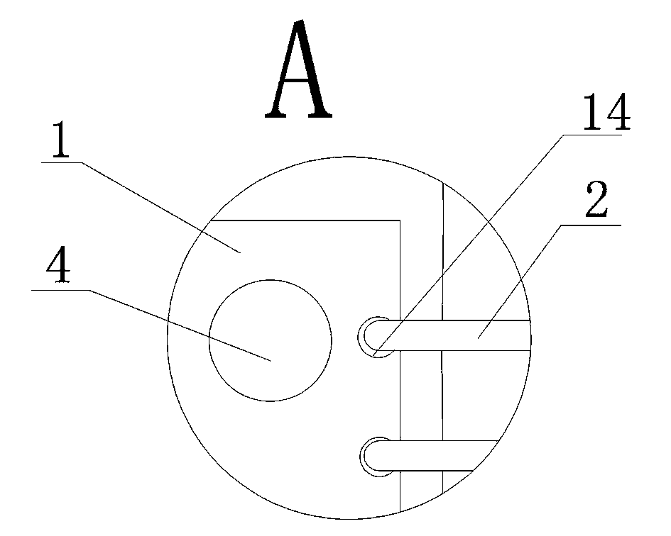
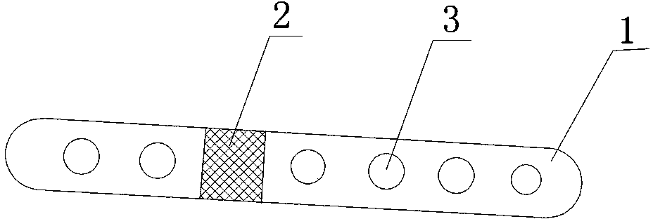
[0028] as attached figure 2 with 3 As shown, when the patient’s lower tibiofibular separation requires osteosynthesis, the movable bone plate provided by the present invention can be used to fix both sides of the bone plate body 1 on the tibia 5 and fibula 6 through screws 4 respectively, and the bone plate body 1 is connected in the middle by a movable connector 2, and the design position of the movable connector 2 corresponds to the micro-motion joint. The movable connector 2 in this embodiment is a rope-like structure, and is fixed on the bone plate body 1 through the connecting hole 14. The bone plate body 1 on the tibia 5 and fibula 6 is connected. In this way, the osteosynthesis plate provided by the present invention can not only meet the demand for rigid bone fixation, but also meet the demand for increased mobility in the fixation of fretting joints, effectively preventing clinical accidents of bone plate fracture or screw slipping out. After surgery, the patient r...

Embodiment 2

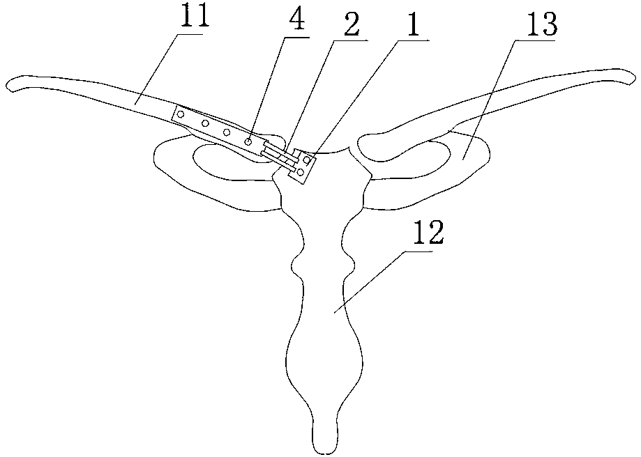
[0030] as attached Figure 4 As shown, when the dislocation of the sternoclavicular joint requires osteosynthesis, the movable bone plate provided by the present invention can be used to fix both sides of the bone plate body 1 to the clavicle 11 and the sternum 12 through screws 4 respectively. 1 is connected by the movable connector 2 in the middle, and the design position of the movable connector 2 corresponds to the micro-motion joint, so that the bone plate provided by the present invention can not only meet the demand for rigid bone fixation, but also meet the fixation of the micro-motion joint The demand for increased mobility effectively prevents the clinical accidents of bone plate fracture or screw slipping out. After surgery, the patient recovered well.

[0031] The movable bone plate provided by the present invention is also suitable for surgical treatment of proximal clavicle fracture, acromioclavicular joint dislocation, and distal clavicle fracture.

[0032] as...


PUM


Abstract

The invention relates to a movable bone connecting plate comprising a bone connecting plate body and a movable connector which are fixedly connected. By the aid of the movable bone connecting plate, under the condition that the shape of the bone connecting plate body is changed rarely, the bone connecting plate has strong strength and movability. The movable bone connecting plate is simple in structure, high in security and adaptable to clinical needs.

Description

technical field [0001] The invention relates to a bone plate, in particular to a movable bone plate. Background technique [0002] At present, bone plates are often used in fracture surgery. Most of the existing bone plates are metal bone plates, which are designed according to the shape of human bones and bionics. The purpose is to minimize the bone bending, compression, and rotation The damage caused by the stress of the product. At the same time, according to the different parts of the product, the shape, thickness, screw hole spacing and hole diameter of the bone plate are predetermined. The most common materials used are medical stainless steel and titanium alloy materials. [0003] Although the existing bone plate can be designed in different shapes according to the different anatomical structures of human bones, the bone plate still cannot meet the problem of synchronous coordination between bone fixation and micro-motion joint movement when fretting joint dislocati...

Claims


Application Information

Patent Timeline
Patent Type & Authority Applications(China)
IPC IPC(8): A61B17/80A61B17/68
Inventor 吴春生吴婷
Owner 吴春生
Why Eureka
Try Eureka