
Vehicle driving apparatus

A driving device and vehicle technology, applied to power devices, pneumatic power devices, vehicle components, etc., can solve problems such as increased loads, and achieve the effect of suppressing changes in rotational speed and suppressing discomfort

Inactive Publication Date: 2013-12-18
AISIN AW CO LTD
View PDF5 Cites 3 Cited by
  • Summary
  • Abstract
  • Description
  • Claims
  • Application Information

AI Technical Summary

Problems solved by technology

Furthermore, if the vehicle continues to run while maintaining the eccentric state, the load acting on the bearings that support each rotating member may increase.

Method used


Image

  • Vehicle driving apparatus
  • Vehicle driving apparatus
  • Vehicle driving apparatus

Examples


no. 1 approach

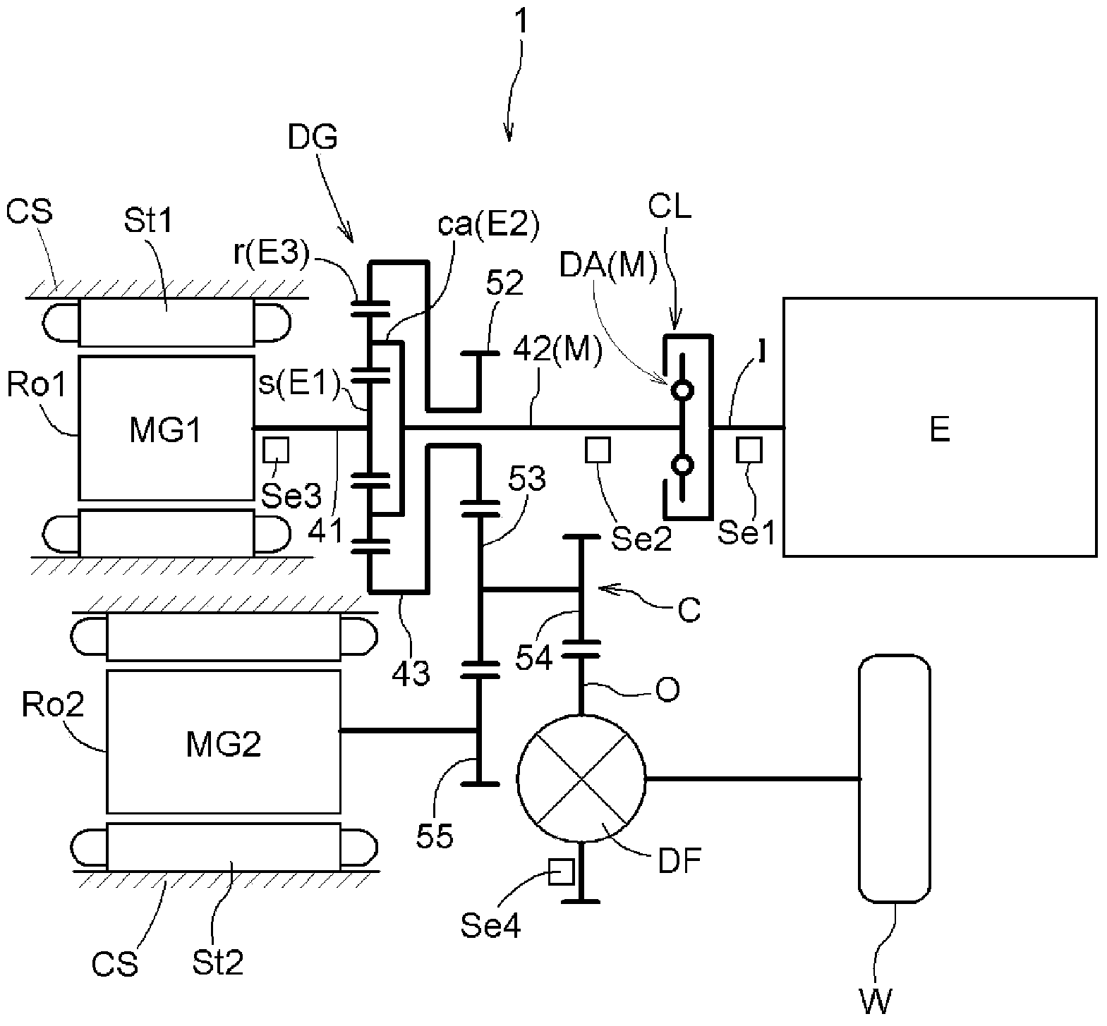
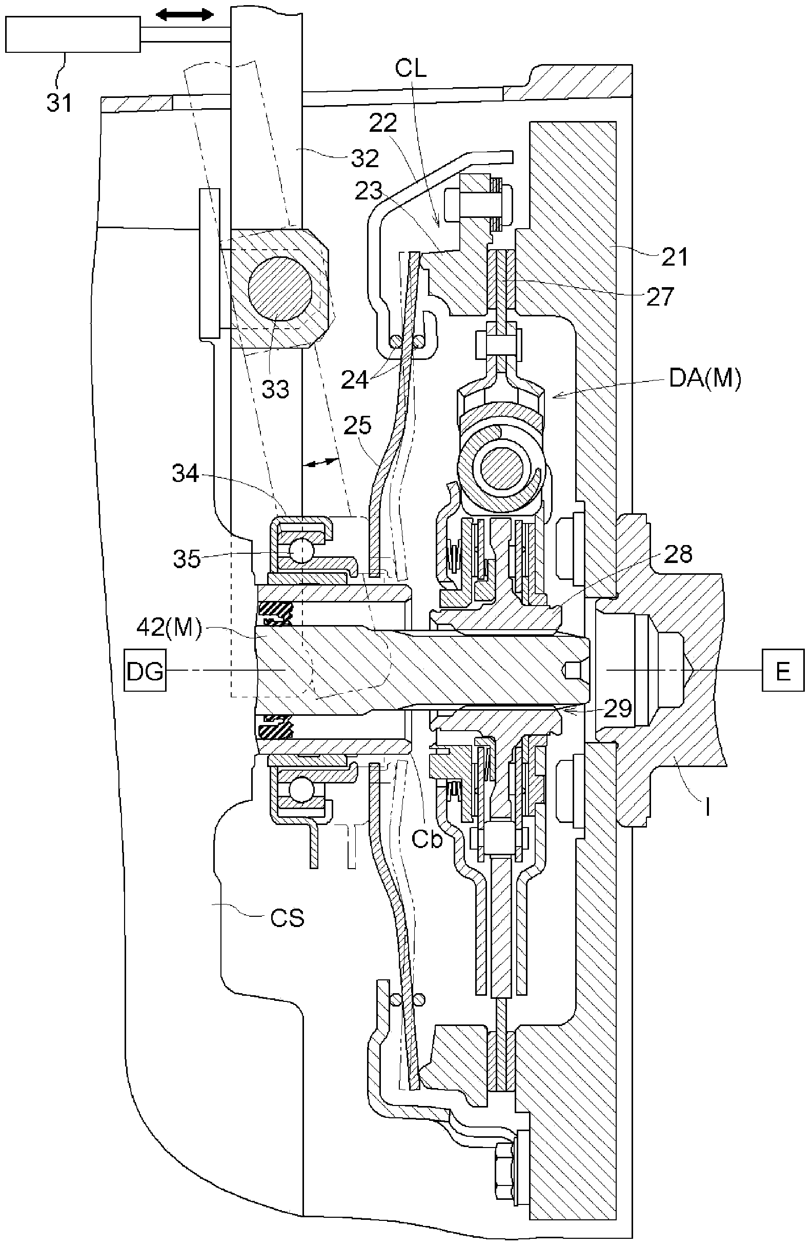
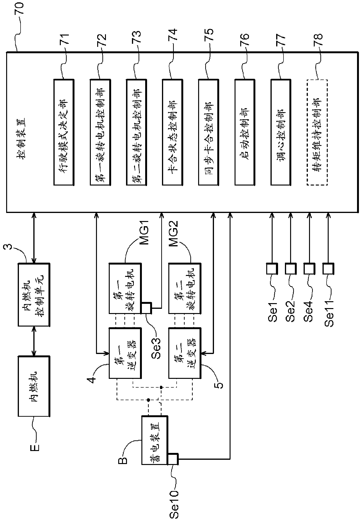
[0038] A first embodiment of a vehicle drive device according to the present invention will be described with reference to the drawings. Such as figure 1 As shown, the vehicle drive device 1 according to the present embodiment is a drive device (hybrid vehicle drive device) for driving a vehicle (hybrid vehicle) provided with an internal combustion engine E and rotary electric machines MG1 and MG2 as drive force sources for wheels W. drive unit). Furthermore, the vehicle drive device 1 according to the present embodiment includes a control device 70 (see image 3 ), the control device 70 is based on image 3 The system configuration shown is used to control the operation of each driving force source and the like. Among them, in image 3 In , the dotted line indicates the transmission path of electric power, and the solid line arrow indicates the transmission path of various information.

[0039] Such as figure 1 As shown, in the present embodiment, the differential gear ...

no. 2 approach

[0124] A second embodiment of the vehicle drive system according to the present invention will be described with reference to the drawings. The vehicle drive device 1 according to the present embodiment differs from the configuration of the above-described first embodiment mainly in the method of determining the completion of the axis center adjustment by the centering control unit 77 and the configuration related thereto. Hereinafter, the configuration of the vehicle drive device 1 according to the present embodiment will be described focusing on differences from the first embodiment described above. However, points not particularly described are the same as those of the first embodiment described above.

[0125] The centering control unit 77 performs the completion determination of the axis center adjustment based on the rotational speed difference ΔN between the input member I and the intermediate member M, at least as in the first embodiment described above. In the presen...


PUM


Abstract

The present invention implements a vehicle driving apparatus capable of suppressing the continuation of an eccentric state between rotating members on both sides of a frictional engagement device while suppressing the occurrence of a shock during the engagement of the frictional engagement device accompanying the starting of an internal combustion engine. A vehicle driving apparatus is provided with an input member coupled to an internal combustion engine (E), an intermediate member coupled to a rotating electric machine (MG1), an output member coupled to a wheel, a frictional engagement device provided between the input member and the intermediate member, and a control device. The control device is provided with a synchronous engagement control unit for synchronously engaging the frictional engagement device when an internal combustion engine starting condition is satisfied in the disengaged state of the frictional engagement device, a starting control unit for starting the internal combustion engine (E) by the torque of the rotating electric machine (MG1), and a centering control unit for decreasing the engagement pressure of the frictional engagement device in an internal combustion engine rotating state, and when detecting that the differential rotation speed (?N) has become a differential rotation threshold value (delta Ns2) or more, performing a centering operation for returning the frictional engagement device to a direct-coupled engaged state.

Description

technical field [0001] The present invention relates to an electric motor comprising an input member drivingly connected to an internal combustion engine, an output member drivingly connected to wheels, an intermediate member drivingly connected to a rotating electric machine in a power transmission path connecting the input member and the output member, and capable of releasing the connection between the input member and the intermediate member. The friction engagement device for driving connection between them, and the vehicle drive device for the control device. Background technique [0002] As the prior art of the vehicle drive device as described above, there is, for example, the technology described in Patent Document 1 below. The device of Patent Document 1 further includes a differential gear device having a sun gear drivingly connected to the first rotating electric machine, a planetary carrier drivingly connected to the intermediate member, and a sun gear drivingly...

Claims


Application Information

Patent Timeline
Patent Type & Authority Applications(China)
IPC IPC(8): B60W10/02B60K6/445B60W10/06B60W10/08B60W20/00F02D29/02B60L50/16
CPCB60K6/387B60K6/445B60W10/02B60W10/08B60W20/40B60W2710/025B60W2710/081F02D29/02Y02T10/62
Inventor 高见重树新智夫山本义久
Owner AISIN AW CO LTD
Learn More