Spot welding apparatus that judges welding state

Active Publication Date: 2018-03-01
FANUC CORP
View PDF2 Cites 5 Cited by
  • Summary
  • Abstract
  • Description
  • Claims
  • Application Information

AI Technical Summary

Benefits of technology

The patent describes a method of spot welding that concentrates the welding current on the weld by maintaining high pressurizing force to the workpiece while supplying electric current. An invention is also described that can detect and control the inclination of the pressurizing force to improve the quality of the weld. The technical effect of this patent is the improved efficiency and quality of spot welding aluminum-based workpieces and similar materials.

Problems solved by technology

However, the welding current may increase beyond the desired value during the period in which the electrode is held at the same position.
As the welding current increases, heat input to the weld increases, resulting in too rapid a growth of the nugget.
In this case, the pressurizing force becomes excessive, which may eventually cause the weld to splash, resulting in spatter.
However, in this control, the correction of the pressurizing force is not completed in the predetermined time and a crack or the like may occur in the weld.

Method used


Image

  • Spot welding apparatus that judges welding state
  • Spot welding apparatus that judges welding state
  • Spot welding apparatus that judges welding state

Examples


Embodiment Construction

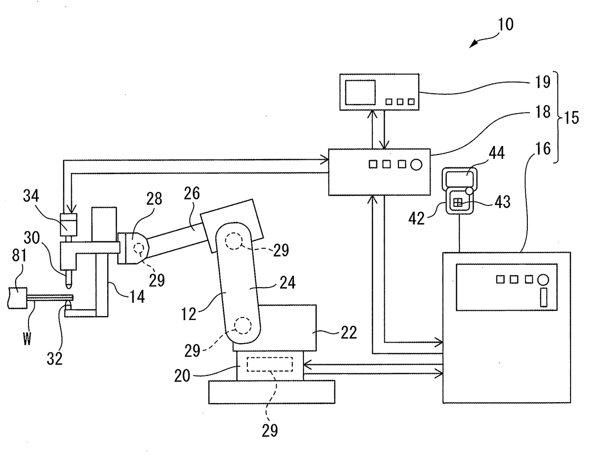
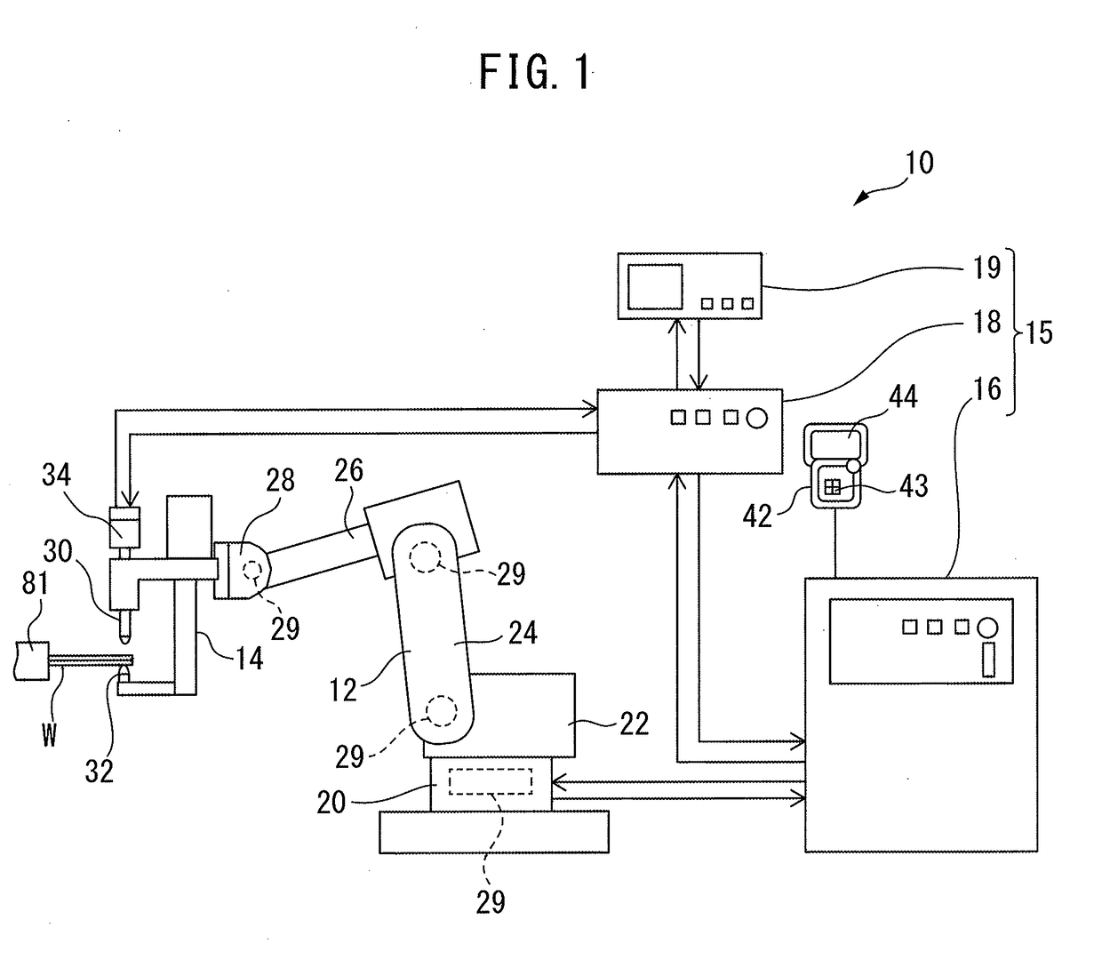
[0026]With reference to FIG. 1 to FIG. 12, a spot welding apparatus according to an embodiment will be described. The spot welding apparatus according to the present embodiment is supported by a robot.

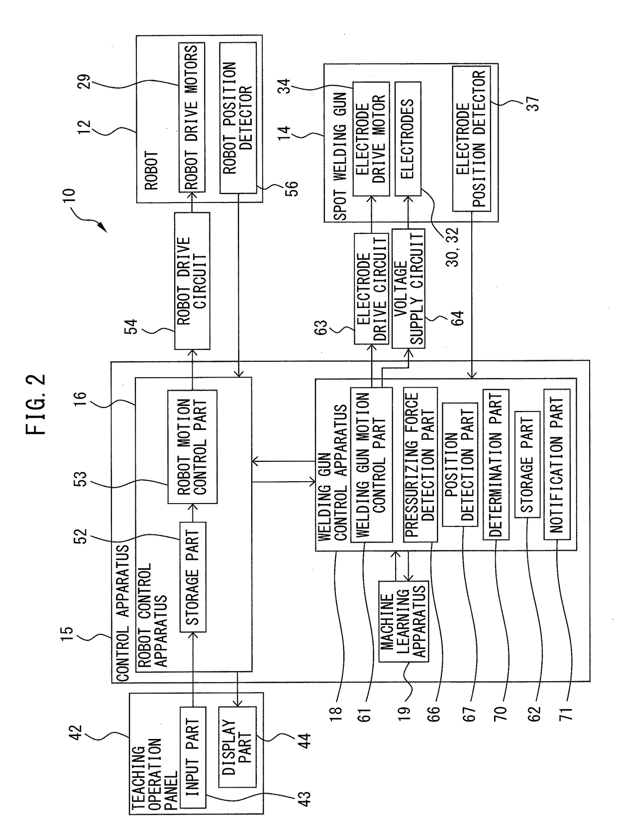
[0027]FIG. 1 shows a schematic diagram of first spot welding apparatus according to the present embodiment. FIG. 2 shows a block diagram of the first spot welding apparatus according to the present embodiment. With reference to FIG. 1 and FIG. 2, the spot welding apparatus 10 according to the present embodiment includes a robot 12 and a spot welding gun 14. The robot 12 according to the present embodiment is an articulated robot having a plurality of joint units. The spot welding apparatus 10 includes a control apparatus 15 that controls the robot 12 and the spot welding gun 14.

[0028]The control apparatus 15 includes a robot control apparatus 16 that controls the robot 12 and a welding gun control apparatus 18 that controls the spot welding gun 14. The robot control apparatus 16 and th...


PUM

PropertyMeasurementUnit
Forceaaaaaaaaaa

Abstract

A spot welding apparatus includes a spot welding gun and a welding gun control apparatus. The welding gun control apparatus includes a pressurizing force control part controlling the pressurizing force, a position control part controlling the position of at least one electrode, and a determination part determining whether or not the welding is performed in a normal state. The position control part controls an electrode drive motor so as to hold the electrodes, after the supply of the electric current is started, at positions when the initial pressurizing force is applied before the electric current is supplied. The determination part acquires the pressurizing force and determines whether or not the welding is performed in a normal state based on change tendency in the pressurizing force.

Description

BACKGROUND OF THE INVENTION1. Field of the Invention[0001]The present invention relates to a spot welding apparatus.2. Description of the Related Art[0002]For joining metal parts in a product manufacturing process, spot welding is conventionally used. For example, in manufacturing a car body, spot welding is used in order to affix parts together. In car manufacturing, efforts have been made for weight reduction of car bodies in order to improve fuel mileage. In a method for reducing the weight, parts that are used in the product can be formed with a light material. In one method for reducing the weight of car bodies, aluminum-based parts can be used instead of conventional iron-based parts. Aluminum-based parts can be joined together by laser beam welding, by friction stir welding, or by adhesives. Spot welding is most commonly used in view of equipment cost or reliability of joined spots.[0003]When joining aluminum-based parts by spot welding, there are different technical problems...

Claims


Application Information

Patent Timeline
IPC IPC(8): B23K11/25B23K11/11G05B13/02
CPCB23K11/255B23K11/115B23K2203/10B23K2201/006G05B13/0265B23K11/314B23K11/36B23K11/185B23K11/315B23K2101/18B23K2101/006B23K2103/10
Inventor AOKI, TOSHIMICHIAMAGATA, YASUHIRO
Owner FANUC CORP
Why Eureka
Try Eureka