Communication device and method of controlling the same
A communication device and communication line technology, applied in digital transmission systems, electrical components, transmission systems, etc., can solve the problems of bandwidth expansion, inability to continue communication, and inability to bundle multiple physical links, etc., to achieve bandwidth expansion and failover time The effect of speeding up
- Summary
- Abstract
- Description
- Claims
- Application Information
AI Technical Summary
Problems solved by technology
Method used
Image
Examples
Embodiment approach 1
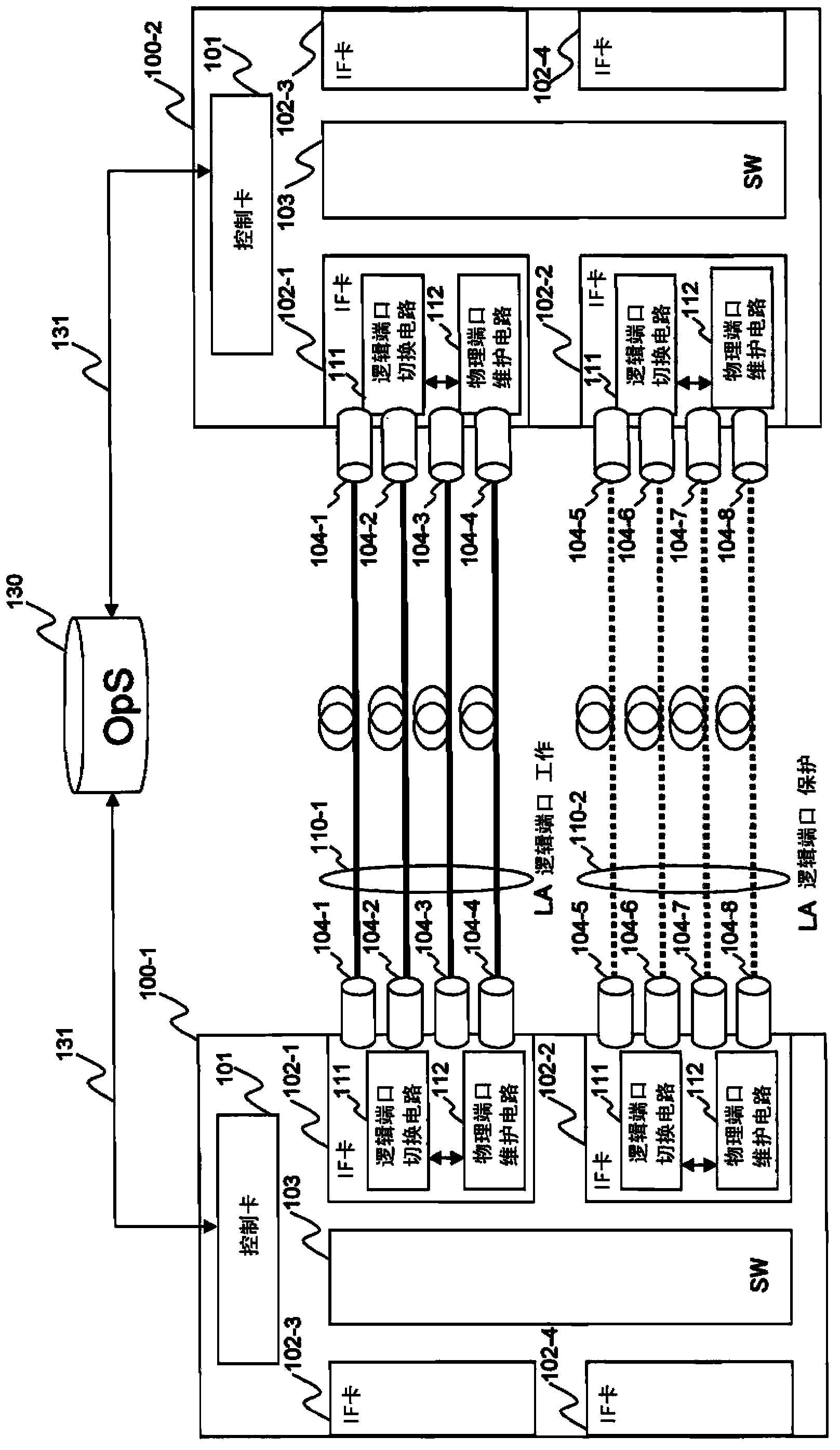
[0044]Hereinafter, a first embodiment of the present invention will be described in detail with reference to the drawings. In this embodiment, a link aggregation method is used as a function of aggregating a plurality of physical ports, but the same effect can be obtained by adopting a method of aggregating a plurality of physical links other than link aggregation. In addition, in this embodiment, Ethernet OAM is used for failure monitoring of physical ports, but the same effect as this embodiment can be obtained by adopting a failure monitoring method other than Ethernet OAM. Similarly, in this embodiment, Ethernet APS is used for switching LA logical ports, but the same effect as this embodiment can be obtained by adopting a redundant path switching method other than Ethernet APS.
[0045] figure 1 It is a block diagram showing the configuration of the communication system according to the first embodiment of the present invention, and specifically shows an example of a co...
Embodiment approach 2
[0181] Hereinafter, a second embodiment of the present invention will be described in detail with reference to the drawings. The structural difference between the second embodiment of the present invention and the first embodiment is that the first embodiment has a 1:1 redundant structure, and the second embodiment has a 1+1 redundant structure. Among the constituent elements of the communication system of the present embodiment, the elements assigned the same reference numerals as the constituent elements of the communication system of the first embodiment have the same reference numerals as those assigned thereto except for the differences described below. The constituent elements of the communication system of the first embodiment of the reference numerals have the same functions, and therefore descriptions thereof will be omitted.
[0182] Figure 16 It is an explanatory diagram of the flow of the Ethernet frame in the communication system according to the second embodime...
Embodiment approach 3
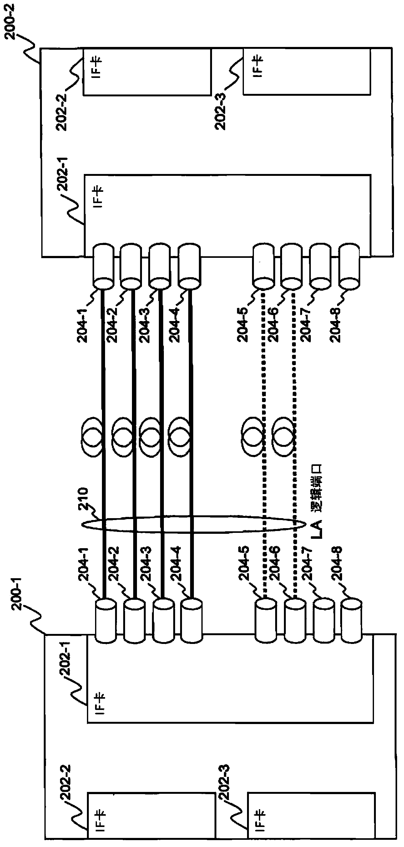
[0213] Hereinafter, a third embodiment of the present invention will be described in detail with reference to the drawings. The structural difference between the third embodiment of the present invention and the first and second embodiments is that in the first and second embodiments, an LA logical port is implemented between adjacent communication devices 100-1 and 100-2. 110-n, in contrast to this, in the third embodiment, there is a communication carrier ( Carrier) in the case of the trunk network to achieve the redundancy of the LA logical port.
[0214] In the third embodiment, an LA logical port is constructed between the remote communication device 500-1 and the communication device 500-2, and the OAM function confirms the normality of the physical port belonging to the LA logical port. In the event of a failure, the communication devices 500 - 1 and 500 - 2 have a remote port maintenance circuit 571 in order to switch the LA logical port by the APS function.
[0215]...
PUM
 Abstract
Description
Claims
Application Information
 - R&D Engineer
- R&D Manager
- IP Professional
- Industry Leading Data Capabilities
- Powerful AI technology
- Patent DNA Extraction
Browse by: Latest US Patents, China's latest patents, Technical Efficacy Thesaurus, Application Domain, Technology Topic, Popular Technical Reports.
© 2024 PatSnap. All rights reserved.Legal|Privacy policy|Modern Slavery Act Transparency Statement|Sitemap|About US| Contact US: help@patsnap.com


