
Amplification circuit for laser distance measuring receiving system

A receiving system and amplifying circuit technology, which is applied in the field of amplifying circuits of laser ranging receiving systems, can solve problems such as AC signal flooding, PIN tube saturation, and failure to extract, so as to improve functional stability, ensure normal operation, and facilitate integration Effect

Active Publication Date: 2013-12-18
CHERY AUTOMOBILE CO LTD
View PDF5 Cites 3 Cited by
  • Summary
  • Abstract
  • Description
  • Claims
  • Application Information

AI Technical Summary

Problems solved by technology

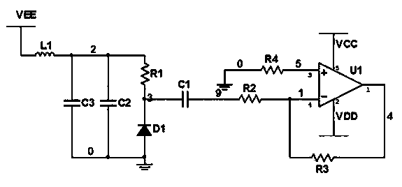
[0004] The present invention designs an amplifying circuit for a laser ranging receiving system. The technical problem it solves is that in the case of sufficient sunshine, the PIN tube is often saturated, and the effective AC signal is submerged and cannot be extracted, resulting in Part of it cannot work effectively, affecting the stability of system functions

Method used


Image

  • Amplification circuit for laser distance measuring receiving system
  • Amplification circuit for laser distance measuring receiving system

Examples


Embodiment Construction

[0012] Combine below figure 2 , the present invention is further described:

[0013] like figure 2 As shown, the signal acquisition circuit includes: PIN tube D1, resistor R1, resistor R2, resistor R3, resistor R4, capacitor C1, capacitor C2, capacitor C3, magnetic bead L1, operational amplifier U1, power supply VEE, power supply VCC and power supply VDD . The power supply VCC and the power supply VDD are the working positive power supply and negative power supply of the operational amplifier U1 respectively, the power supply VEE is connected to one end of the magnetic bead L1, the other end of the magnetic bead L1 is connected to one end of the resistor R1, and the other end of the resistor R1 is connected to the pin of the PIN tube D1 The cathode, the anode of the PIN tube D1 is grounded, the capacitor C2 and the capacitor C3 are connected in parallel between the bead L1 and the resistor R1, the cathode of the PIN tube D1 is connected to one end of the capacitor C1 at th...


PUM


Abstract

The invention relates to an amplification circuit for a laser distance measuring receiving system. A power supply VCC and a power supply VDD are respectively a positive power supply and a negative power supply for the work of an operation amplifier U1, the power supply VEE is connected with one end of a magnetic ball L1, the other end of the magnetic ball L1 is connected with one end of a resistor R1, the other end of the resistor R1 is connected with a cathode of a PIN tube D1, an anode of the PIN tube D1 is grounded, a capacitor C2 and a capacitor C3 are connected in parallel between the magnetic ball L1 and the PIN tube D1, the cathode of the PIN tube D1 is connected with one end of the capacitor C1, a resistor R2 is connected in series between the capacitor C1 and the reverse phase input end of the operation amplifier U1, the resistor R3 is connected in series between the reverse phase input end and the output end of the operation amplifier U1, one end of a resistor R4 is connected with the identical phase input end of the operation amplifier U1, and the other end of the resistor R4 is grounded. The amplification circuit is adopted for preventing the saturation phenomenon of the receiving PIN tube, and the normal work of the receiving circuit is ensured, so the function stability of the laser distance measuring system is improved.

Description

technical field [0001] The invention relates to an amplifying circuit, in particular to an amplifying circuit of a laser ranging receiving system. Background technique [0002] At present, laser ranging technology has been widely used in the field of automotive active safety. [0003] The laser ranging system mainly includes a transmitting part and a receiving part, such as figure 1 As shown, the receiving part usually includes PIN tube, amplifier, filter circuit and timing chip. Normally, the amount of charge flowing in the PIN tube is determined by the light intensity and the voltage difference between the two ends. In the case of sufficient sunlight, the PIN tube is often saturated, that is, the charge flowing through the PIN tube is no longer changing but a constant value, and the effective AC signal is submerged and cannot be extracted, resulting in the receiving part not working effectively. Affect the stability of system functions. Contents of the invention [0...

Claims


Application Information

Patent Timeline
Patent Type & Authority Applications(China)
IPC IPC(8): H03F3/20
Inventor 段山保李济林周宏
Owner CHERY AUTOMOBILE CO LTD
Learn More