Suspension type vibration-proof structure

An anti-vibration structure and suspension technology, which is applied in the direction of anti-vibration, building components, etc., can solve problems such as difficult to realize, and achieve the effects of low power consumption, high efficiency, and reduced seismic force

Inactive Publication Date: 2013-12-18
夏昌 +3
View PDF5 Cites 0 Cited by
  • Summary
  • Abstract
  • Description
  • Claims
  • Application Information

AI Technical Summary

Problems solved by technology

The sandwich rubber cushion isolation technology of existing building construction can only partially eliminate the impact of earthquake, wind and other possible vibrations on buildings and their internal facilities, and the existing rubber cushion and air cushion vibration isolation techniques cannot completely eliminate mechanical equipment vibration. The disturbance caused by vibration to the surrounding environment
In the field of high-rise or super high-rise buildings, not only the adverse effects of wind and earthquake are more serious, but also the application of the above-mentioned vibration reduction and isolation (seismic) technology is difficult to realize due to technical limitations.

Method used


Image

  • Suspension type vibration-proof structure
  • Suspension type vibration-proof structure
  • Suspension type vibration-proof structure

Examples


Embodiment 1

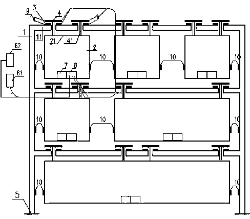
[0025] Embodiment 1: as figure 1 Shown is the principle diagram of the repulsive suspension structure of the present invention.

[0026] In this embodiment, the substructure magnets (4) and magnets (3) adopt electromagnets, which means that several substructures (2) are made in the engineering structure (1), above the top (21) of the substructure (2) A substructure magnet (4) is formed, and a magnet (3) is formed above or below the structural beam or plate (11) of the engineering structure (1) corresponding to the substructure magnet (4); and the engineering structure (1) and A control device is formed between the substructures (2). Wherein, the substructure magnet (4) is connected to the top (21) of the substructure (2) through a connecting rod (41) passing through the structural beam or plate (11), and placed above the magnet (3) ; The magnet (3) is fabricated above the structural beam or plate (11); and the substructure magnet (4) and the magnet (3) have the same electrom...

Embodiment 2

[0032] Embodiment 2: as image 3 Shown is the principle diagram of another embodiment of the repulsive suspension structure of the present invention.

[0033] In this embodiment, the substructure magnets (4) and magnets (3) adopt electromagnets, which means that several substructures (2) are made in the engineering structure (1), above the top (21) of the substructure (2) A substructure magnet (4) is formed, and a magnet (3) is formed above or below the structural beam or plate (11) of the engineering structure (1) corresponding to the substructure magnet (4); and the engineering structure (1) and A control device is formed between the substructures (2). Among them, the substructure magnet (4) is connected with the top (21) of the substructure (2) through the connecting rod (41), and placed above the magnet (3), and the magnet (3) is connected through the connecting piece (31 ) is connected to the underside of the structural beam or plate (11); and the substructure magnet (4...

Embodiment 3

[0034] Embodiment 3, as Figure 4 Shown is the principle diagram of the suction type suspension structure of the present invention.

[0035]In this embodiment, the substructure magnets (4) and magnets (3) adopt electromagnets, which means that several substructures (2) are made in the engineering structure (1), above the top (21) of the substructure (2) A substructure magnet (4) is formed, and a magnet (3) is formed above or below the structural beam or plate (11) of the engineering structure (1) corresponding to the substructure magnet (4); and the engineering structure (1) and A control device is formed between the substructures (2). Among them, the substructure magnet (4) is directly fabricated on the top (21) of the substructure (2) and placed under the magnet (3), and the magnet (3) is also directly fabricated on the structural beam or plate (11 ) below; and the electromagnetic polarities of the opposite faces of the substructure magnet (4) and magnet (3) are opposite w...


PUM


Abstract

The invention relates to buildings and vibration-proof (quake-proof) measures for internal facilities of the buildings, and particularly belongs to a suspension type vibration-proof structure. The technical scheme includes that a plurality of sub-structures (2) are arranged in an engineering structure (1), sub-structure magnets (4) are arranged above tops (21) of the sub-structures (2), and magnets (3) are arranged above or below structural beams or slabs (11) of the engineering structure (1) and correspond to the sub-structure magnets (4); control devices are arranged among the engineering structure (1) and the sub-structures (2). The suspension type vibration-proof structure has the advantages that the suspension type vibration-proof structure is completely free of abrasion and pollution and can be used for a long time; the suspension type vibration-proof structure is completely free of mechanical friction, and is low in power consumption and noise and high in efficiency, and lubrication and sealing are omitted; electromagnetic force is controllable and adjustable, the sub-structures can be assuredly in balanced states without vibration, and active control for vibration is facilitated; all movement characteristics of suspended matters can be acquired by position sensors, so that running states can be diagnosed and monitored conveniently.

Description

[0001] technical field [0002] The invention relates to anti-vibration (earthquake) of buildings and internal facilities thereof, in particular to a suspension type anti-vibration structure. Background technique [0003] Engineering vibration can be divided into harmful vibration and harmless vibration. It is always an engineering technology research to control the forced vibration of engineering (such as the vibration generated by wind, earthquake and other external forces) and to isolate the adverse impact of vibration (such as the vibration generated by the operation of mechanical equipment) on the outside world. hotspots. The sandwich rubber cushion isolation technology of existing building construction can only partially eliminate the impact of earthquake, wind and other possible vibrations on the building and its internal facilities, and the existing rubber cushion and air cushion vibration isolation techniques cannot completely eliminate mechanical equipment. The d...

Claims


Application Information

Patent Timeline
Patent Type & Authority Applications(China)
IPC IPC(8): E04B1/98
Inventor 夏昌张移生黄滨张建祥
Owner 夏昌
Why Eureka
Try Eureka