


Quick Research
Generate reliable direction feasibility study reports for your R&D in just a few steps.

Technical Q&A
Discover and master advanced knowledge NOW. Basics, ideas, possibilities, all at once.

Find Solutions
As an expert in R&D theories, this can generate solutions to your technical problems instantly.

Evaluate Feasibility
Analyze your overall solution with one click, know your potential R&D risks in advance.

Monitor Landscape
Get weekly tech updates, stay abreast of the latest tech innovations and key insights.
A Low Friction Reservoir Protection Cement Slurry
A technology of reservoir protection and cement slurry, which is applied in the field of oilfield drilling and cementing, can solve problems such as high hydrostatic column pressure of cement slurry, formation rupture, and formation blocking, so as to save production costs, maintain integrity, and have good elastic-plastic properties Effect
- Summary
- Abstract
- Description
- Claims
- Application Information
AI Technical Summary
Problems solved by technology
Method used
Image

Examples
Embodiment 1
[0040] A kind of low-friction reservoir protection cement slurry (1.80g / cm 3 ), including 100 parts of G grade oil well cement; 69 parts of fresh water; 24 parts of fly ash; 26 parts of reinforcing agent PC-BT3; 6 parts of fluid loss reducing agent PC-G80L; Foaming agent PC-X60L.
[0041] Its preparation method refers to the fifth part of "Oil Well Cement Test Method" in "GB / T19139-2003", which is "Preparation of Cement Slurry".
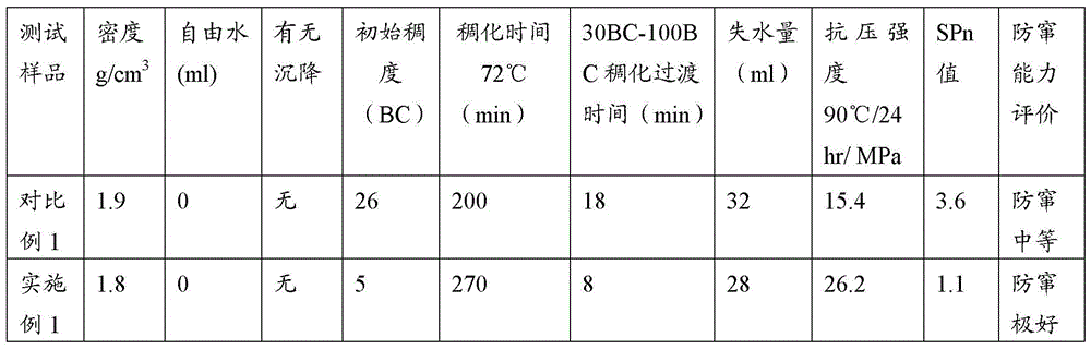
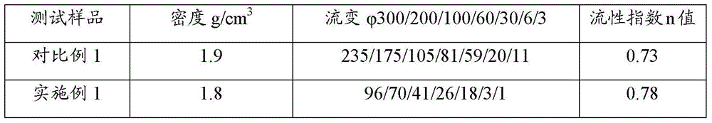
[0042]In order to better reflect the performance advantages of the cement slurry described in the application, the following cement slurry (1.90g / cm 3 ) as comparative example 1, which includes 800 parts of G grade oil well cement; 307.9 parts of fresh water; 50 parts of PC-G75L; 3.5 parts of PC-H21L; 4 parts of defoamer PC-X60L.
[0043] Test Conditions and Results
[0044] 1, the cement slurry in embodiment 1 and comparative example 1 is carried out system performance test respectively, obtains the result as shown in table 1:
[0045] Table 1 s...
Embodiment 2
[0073] A low-friction reservoir protection cement slurry (1.70g / cm 3 ), including 100 parts of G grade oil well cement; 115 parts of fresh water; 50 parts of fly ash; 35 parts of reinforcing agent PC-BT3; 6 parts of fluid loss reducing agent PC-G80L; 2 parts of retarder PC-H41L; 40 parts of silica Powder; 0.5 parts of defoamer PC-X60L. This formula is suitable for use when the static temperature at the bottom of the well is 150-160°C.
[0074] Its preparation method refers to the fifth part of "Oil Well Cement Test Method" in "GB / T19139-2003", which is "Preparation of Cement Slurry".
Embodiment 3
[0076] A low-friction reservoir protection cement slurry (1.70g / cm 3 ), including 100 parts of G grade oil well cement; 113 parts of fresh water; 58 parts of fly ash; 52 parts of reinforcing agent PC-BT3; 3 parts of fluid loss reducing agent PC-G80L; 0.5 parts of defoamer PC-X60L. This formula is suitable for use when the static temperature at the bottom of the well is 40-50°C.
[0077] Its preparation method refers to the fifth part of "Oil Well Cement Test Method" in "GB / T19139-2003", which is "Preparation of Cement Slurry".
PUM
| Property | Measurement | Unit |
|---|---|---|
| Elastic modulus | aaaaa | aaaaa |
Abstract
Description
Claims
Application Information
 - R&D Engineer
- R&D Manager
- IP Professional
- Industry Leading Data Capabilities
- Powerful AI technology
- Patent DNA Extraction
Browse by: Latest US Patents, China's latest patents, Technical Efficacy Thesaurus, Application Domain, Technology Topic, Popular Technical Reports.
© 2024 PatSnap. All rights reserved.Legal|Privacy policy|Modern Slavery Act Transparency Statement|Sitemap|About US| Contact US: help@patsnap.com