heating circulation pump

A heating cycle, pump housing technology, applied in the direction of pumps, pump devices, non-variable-capacity pumps, etc., to achieve the effect of beautiful design, conducive to packaging and storage, and reducing the diversity of parts

Active Publication Date: 2017-11-21
GRUNDFOS MANAGEMENT AS
View PDF1 Cites 0 Cited by
  • Summary
  • Abstract
  • Description
  • Claims
  • Application Information

AI Technical Summary

Problems solved by technology

[0003] Such small to medium heating circulators are already produced in high volumes, so even the smallest improvements can mean huge savings in manufacturing and / or assembly

Method used


Image

  • heating circulation pump
  • heating circulation pump
  • heating circulation pump

Examples


Embodiment Construction

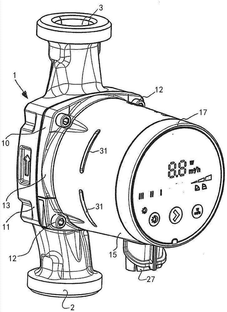
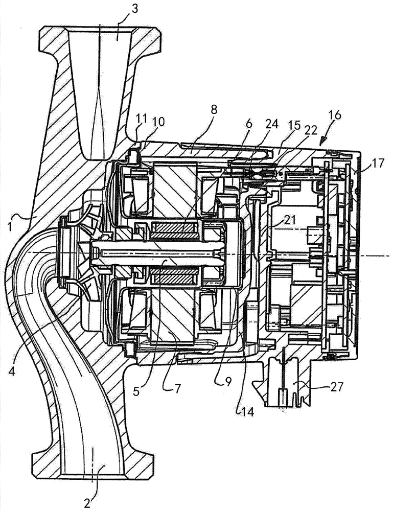
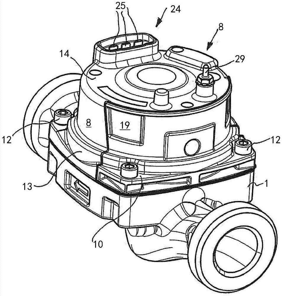
[0027]The heating circulation pump shown in the figure has a pump housing 1 comprising a suction sleeve 2 and a pressure sleeve 3 . A pump impeller 4 is rotatably arranged in the pump housing 1 in order to convey the conveying liquid at high pressure from the suction sleeve 2 into the pressure sleeve 3 in a known manner by rotating the pump impeller 4 . The pump impeller 4 is arranged on the shaft 5 , which simultaneously carries the rotor 6 of the electric motor, and the stator 7 of the electric motor is arranged in the stator housing 8 . The motor is a wet-running motor and has a liquid-filled slot 9 between the rotor 6 and the stator 7 .

[0028] The pump housing 1 is designed to be open relative to the stator housing 8 . At its pump-side end, the stator housing 8 has a flange 10 which is connected to a flange 11 of the pump housing 1 and has a rounded square contour. Due to the circular design of the other part of the stator housing 8 , there will be a part in which the ...


PUM


Abstract

The invention relates to a heating circulation pump, comprising: a pump housing (1) and at least one pump impeller (4) arranged in the pump housing, the pump impeller being driven by an electric motor (6, 7), the motor The stator housing (8) has a flange which is connected to the pump housing (1). The heating circulation pump has a terminal box housing (15) for the electrical connection of the electric motors (6, 7). The terminal box housing ( 15 ) overlaps the stator housing ( 8 ) from the side facing away from the pump up to the flange.

Description

technical field [0001] The invention relates to a heat supply circulating pump. Background technique [0002] Such heating circulation pumps are known in the prior art. They generally comprise a pump housing with a suction sleeve and a pressure sleeve and an impeller arranged in the pump housing. An electric motor is provided to drive the pump impeller, and the shaft of the electric motor carries the pump impeller. The stator surrounding the rotor is arranged in a housing which has a flange or similar connecting element on its side facing the pump housing, via which the motor housing, in particular the stator housing, is connected to the pump housing. connect. A terminal box housing is provided for the electrical connection of the electric motor, which is arranged on the axial side of the stator housing facing away from the pump housing and forms the lower part of the terminal box. The terminal box housing usually also contains the motor electronics, such as a frequency ...

Claims


Application Information

Patent Timeline
Patent Type & Authority Patents(China)
IPC IPC(8): F04D13/06H02K5/00
CPCH02K5/225F04D13/064H02K11/33H02K5/04F04D13/0693
Inventor 米克尔·林德·斯滕托夫特
Owner GRUNDFOS MANAGEMENT AS
Why Eureka
Try Eureka