
Electronic current transformer short-time current vibration test device and method thereof

A technology of current transformer and short-time current, which is applied in the field of vibration test device for primary parts during the short-time current of electronic current transformer, can solve the problems such as no test method is proposed, and achieve the effect of simple structure and accurate data measurement

Active Publication Date: 2013-12-11
STATE GRID CORP OF CHINA +2
View PDF5 Cites 8 Cited by
  • Summary
  • Abstract
  • Description
  • Claims
  • Application Information

AI Technical Summary

Problems solved by technology

[0005] According to the requirements of GB / T20840.8-2007, when the electronic current transformer is subjected to the vibration of electromagnetic force during the short-term current, the electronic current transformer should maintain a normal output state, but the standard does not propose a specific test method

Method used


Image

  • Electronic current transformer short-time current vibration test device and method thereof
  • Electronic current transformer short-time current vibration test device and method thereof

Examples


Embodiment 1

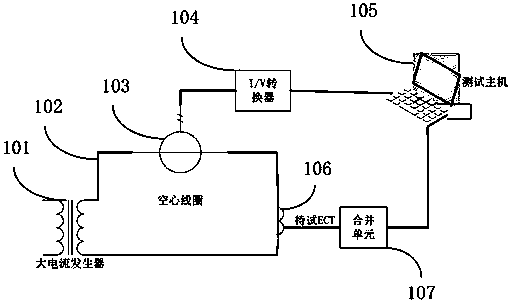
[0027] See attached figure 1 , discloses an electronic current transformer short-time current vibration test device according to the present invention. The devices include:

[0028] A large current generator 101 is used to provide a short-term large current, and is rigidly connected to the ECT106 to be tested by a connecting wire 102;

[0029] The air-core coil 103 passes through the connecting wire 102, and is used to measure the size and time of the short-term current through the ECT106 to be tested;

[0030] The I / V converter 104 is used to convert the current signal output by the secondary winding of the air-core coil into a voltage signal, and transmit it to the test host 105 for host acquisition and triggering;

[0031] The ECT106 to be tested is rigidly connected to the connecting wire 102 and connected to the merging unit 107;

[0032] The test host 105 is used to receive the signal output by the merging unit 107 of the ECT to be tested, and collect the voltage sign...

Embodiment 2

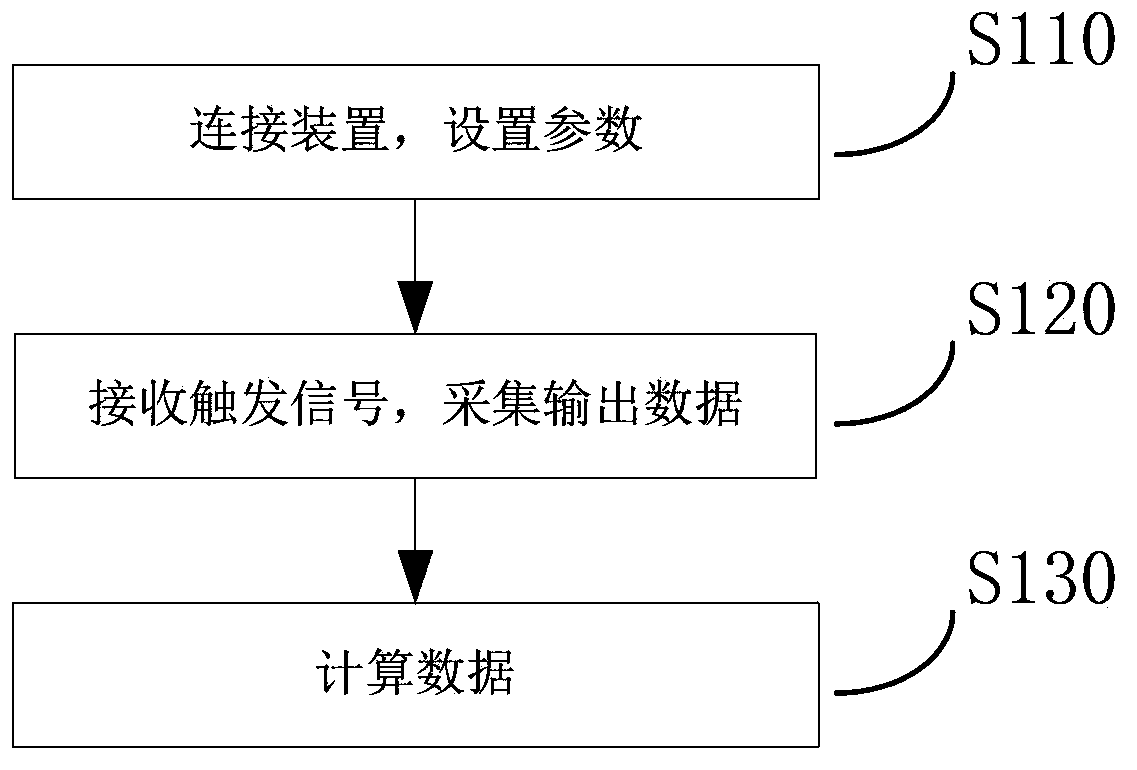
[0037] See attached figure 2 , discloses an electronic current transformer short-term current vibration test method according to an embodiment of the present invention, which is used for the electronic current transformer short-term current vibration test device disclosed in Example 1, comprising the following steps:

[0038] S110: press figure 2 The vibration test device is connected in the manner shown, and the test host is set to output data communication protocol type, rated primary current value, rated secondary output, channel number and other information of the merging unit;

[0039] S120: The large current generator outputs the short-term current required for the test, and the test host starts to collect the output data of the merging unit by receiving the signal of the I / V converter as a trigger signal, and records the merging unit's output data within 10s. Output Data;

[0040] S130. According to the synchronous collection of the trigger signal and the output dat...


PUM


Abstract

The invention provides an electronic current transformer short-time current vibration test device and a method of the electronic current transformer short-time current vibration test device. The test device comprises a large-current generator, a hollow coil, an I / V converter, an ECT to be tested and a test host. The test host continuously records and stores data of a merging unit for more than 10s, at least simultaneously records more than three channels output by the same merging unit, and supports IEC61850-9-1 and IEC61850-9-2LE standards, wherein the channels for storing data can be selected. According to the electronic current transformer short-time current vibration test device and the method of the electronic current transformer short-time current vibration test device, a vibration test can be conducted on primary components of the ECT during the short-time current period, the structure is simple, data can be accurately measured, and the requirement of GB / T20840.8-2007 can be well met.

Description

technical field [0001] The invention relates to a vibration test of an electronic current transformer, in particular to a vibration test device and a test method for a primary component of an electronic current transformer during a short-time current period. Background technique [0002] With the proposal of the State Grid Corporation to build a strong smart grid, various equipment used in the power system is developing in the direction of intelligence, and electronic transformers are being widely used in the power system due to their advantages. Smart substation is an important part of smart grid, and the application of electronic current transformer (ECT) is one of the important signs of intelligent primary equipment in smart substation. The rapid development of smart substations has promoted the progress of the practicality and productization of electronic transformers. [0003] Compared with traditional transformers, electronic current transformers have more components ...

Claims


Application Information

Patent Timeline
Patent Type & Authority Applications(China)
IPC IPC(8): G01R35/02G01M7/02
Inventor 张勤叶国雄郭克勤胡蓓黄华刘彬童悦刘翔金建伟万罡冯翔翔王晓周黄志斌陈鹏杨帆邬文亮邓小聘王焱代静汪英英
Owner STATE GRID CORP OF CHINA
Learn More