
Continuous feeding vent device for cracking furnace

A technology of gas outlet device and cracking furnace, which is applied in the gasification of granular/powdered fuel, manufacture of combustible gas, petroleum industry, etc. It can solve the problems of low feed efficiency, small diameter of feed channel, blockage of gas outlet channel, etc.

Active Publication Date: 2013-12-11
潍坊金丝达环境工程股份有限公司
View PDF6 Cites 0 Cited by
  • Summary
  • Abstract
  • Description
  • Claims
  • Application Information

AI Technical Summary

Problems solved by technology

[0002] Most of the cracking devices in the prior art use a cracking kettle, and its disadvantages are: continuous production is not possible, heating and cracking after filling is completed, cooling the cracking kettle after the cracking is completed, removing coke residue, and then refilling, and the cracking kettle is repeatedly cooled-heated-reloaded. The cooling-reheating working process wastes a lot of energy, the cost of cracking is high, and the cracking efficiency is low
The disadvantage of the feed and gas outlet device of this patent application is that the diameter of the feed channel is small, the feed efficiency is low, and the gas outlet channel is easily blocked by condensed oil and gas, which requires frequent shutdown and cleaning, which greatly reduces the cracking production efficiency.

Method used


Image

  • Continuous feeding vent device for cracking furnace
  • Continuous feeding vent device for cracking furnace
  • Continuous feeding vent device for cracking furnace

Examples


Embodiment Construction

[0019] Below in conjunction with accompanying drawing and embodiment, further elaborate the present invention. In the following detailed description, certain exemplary embodiments of the invention are described by way of illustration only. Needless to say, those skilled in the art would realize that the described embodiments can be modified in various different ways, all without departing from the spirit and scope of the present invention. Accordingly, the drawings and description are illustrative in nature and not intended to limit the scope of the claims.

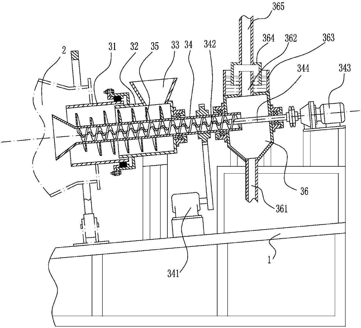
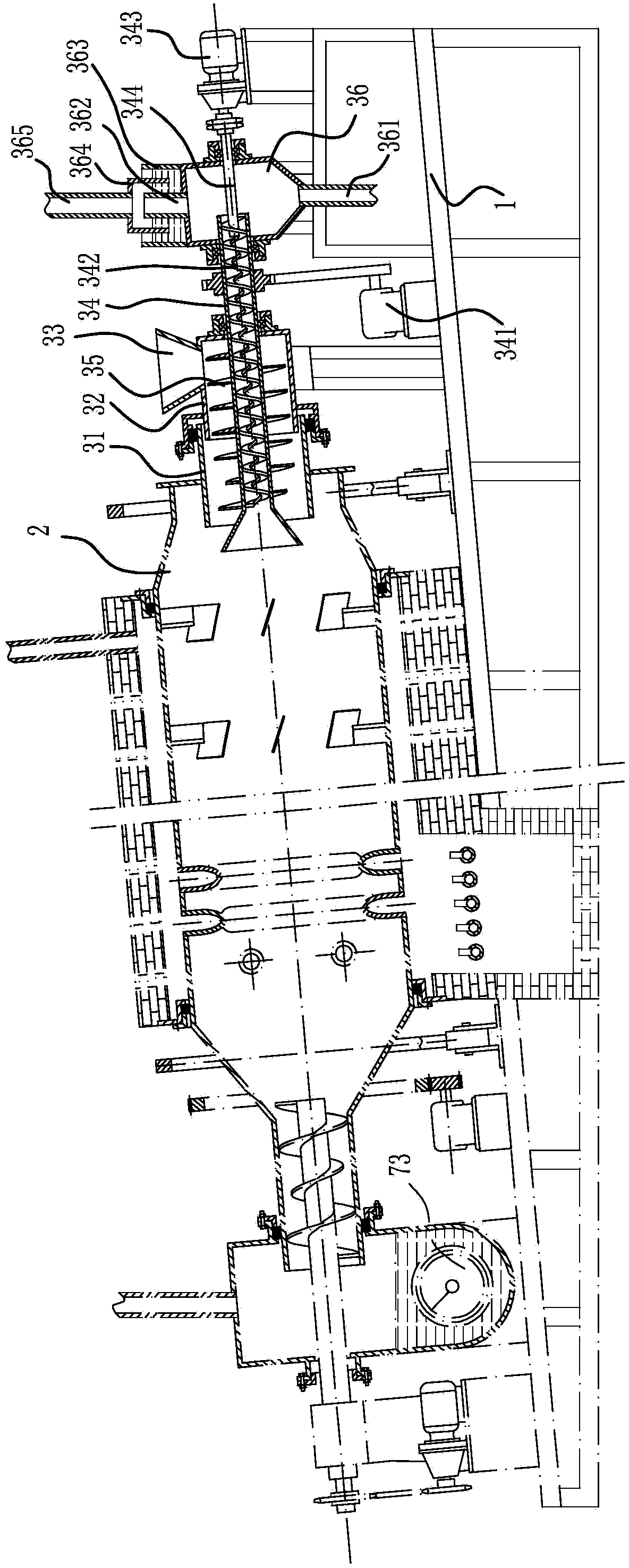
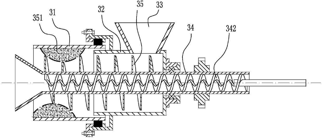
[0020] Such as figure 1 and figure 2 As shown, the cracking furnace is connected with the cracking furnace furnace body 2 with a continuous feed and gas outlet device, and includes a base 1. A screw conveyor shell is installed on the base 1, and a screw conveyor shell is installed above the screw conveyor shell. Feeding hopper 33, the screw conveyor housing extends into the cracking furnace furnace body 2; The air gu...


PUM


Abstract

The invention discloses a continuous feeding vent device for a cracking furnace. The vent device comprises a base, wherein a spiral conveyor shell is installed on the base and extends into a cracking furnace body; a gas guide cylinder penetrating through the spiral conveyor shell and extending into the cracking furnace body is arranged on an axis of the spiral conveyor shell; a feeding auger is fixed on the peripheral surface of the gas guide cylinder; a gas collection tank is installed at the outer end of the gas guide cylinder; a gas guide cylinder rotation driving device is arranged on the gas guide cylinder; a gas guide cylinder deashing auger is installed in the gas guide cylinder; a deashing driving device is installed on the base. The vent device has the beneficial effects that the sectional area of the feeding channel is large, the feeding efficiency is high and the sealability is good; the gas guide cylinder of a vent channel is provided with the deashing auger, thus ensuring smooth venting and avoiding safety accidents caused by blockage; the gas guide cylinder also serves as the auger shaft of the feeding auger, so that the structure of the vent device is compact and the work efficiency is greatly improved.

Description

technical field [0001] The invention relates to a cracking reaction device, in particular to a feed and gas outlet device of the cracking reaction device. Background technique [0002] Most of the cracking devices in the prior art use a cracking kettle, and its disadvantages are: continuous production is not possible, heating and cracking after filling is completed, cooling the cracking kettle after the cracking is completed, removing coke residue, and then refilling, and the cracking kettle is repeatedly cooled-heated-reloaded. The cooling-reheating working process wastes a lot of energy, the cost of cracking is high, and the cracking efficiency is low. [0003] In order to solve the above technical problems, the inventor filed a patent application with the patent application number "201310016317.X" and the patent name "Plastic Recycling Continuous Gasification Cracking Multi-effect Furnace", which completely solved the technical problems existing in the prior art. The dis...

Claims


Application Information

Patent Timeline
IPC IPC(8): C10J3/00C10J3/30C10J3/50C10J3/56C10J3/82C10G1/00
Inventor 刘国田李振衡张大鹏
Owner 潍坊金丝达环境工程股份有限公司
Learn More