
Machining process for longitudinal beam of heavy truck

A heavy-duty vehicle and longitudinal beam technology, which is applied in the field of automobile manufacturing, can solve problems such as increased procedures, poor operating efficiency, and increased difficulty in longitudinal beam processing, and achieves the effect of strong versatility and high efficiency

Active Publication Date: 2013-12-11
SINO TRUK JINAN POWER
View PDF3 Cites 7 Cited by
  • Summary
  • Abstract
  • Description
  • Claims
  • Application Information

AI Technical Summary

Problems solved by technology

With market competition, more and more heavy-duty vehicle frame assemblies adopt structures with unequal widths front and rear, which increases the difficulty of longitudinal beam processing, and increases the number of operating procedures, resulting in poor operating efficiency.

Method used


Image

  • Machining process for longitudinal beam of heavy truck

Examples


Embodiment 1

[0028] The processing method of the heavy-duty vehicle longitudinal beam is divided into the steps of marking - punching - cutting - shot blasting - bending.

[0029] The specific steps are as follows:

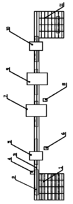
[0030] Marking: The feeding device 1 and the feeding device 3 send the profile of the longitudinal beam 2 to the marking station, position the front end and the belly of the longitudinal beam 2, and the intelligent coding machine 4 marks the longitudinal beam at the lower wing surface of the front end of the frame longitudinal beam After the identification code; increase the traceability of the stringer by marking.

[0031] Punching: The feeding device 3 sends the longitudinal beam 2 to the punching station, and the front end of the longitudinal beam 2 and the lower wing surface are positioned, and the hole position and aperture program of the input longitudinal beam is called through the punching machine control device 6, and the three-dimensional numerical control punching ...

Embodiment 2

[0037] The processing method of the heavy-duty vehicle longitudinal beam is divided into the steps of marking - punching - cutting - shot blasting - bending.

[0038] The specific steps are as follows:

[0039] Marking: The feeding device 1 and the feeding device 3 send the profile of the longitudinal beam 2 to the marking station, position the front end and the belly of the longitudinal beam 2, and the intelligent coding machine 4 marks the longitudinal beam at the lower wing surface of the front end of the frame longitudinal beam After the identification code; increase the traceability of the stringer by marking.

[0040] Punching: The feeding device 3 sends the longitudinal beam 2 to the punching station, and the front end of the longitudinal beam 2 and the lower wing surface are positioned, and the hole position and aperture program of the input longitudinal beam is called through the punching machine control device 6, and the three-dimensional numerical control punching ...


PUM


Abstract

The invention belongs to the field of manufacturing of automobiles, and particularly discloses a machining process for a longitudinal beam of a heavy truck. The machining process for the longitudinal beam of the heavy truck is characterized by comprising the following steps: marking; punching; cutting; shot blasting; bending. The machining process has high universality and high efficiency; coding of an intelligent coding machine, numerical control punching, cutting of a robot plasma cutter and shot blasting are all controlled through programs, so that the specification and the length of a section of the longitudinal beam in a certain range, the size and the position of the hole and the machining of the contour of the longitudinal beam can be realized. Trail production and large-scale and multi-species continuous production can be realized. The precision is high; the positioning is consistent; the positioning at all the punching, cutting and bending processes is realized by the front end of the longitudinal beam; the machining is controlled through the program; a three-dimensional numerical control punching machine is adopted as the punching machine, and wing surface holes and ventral surface holes are finished in sequence to reduce the positioning frequency; the shot blasting is performed to remove scales and rust before bending so as to eliminate the influence of the scales on bending.

Description

technical field [0001] The invention belongs to the field of automobile manufacturing, in particular to a processing method for a longitudinal beam of a heavy automobile. Background technique [0002] The frame stringer of a heavy-duty vehicle is an important basic part of the car. The stringer is arranged on the left and right sides of the car frame. The bending strength of the car body is mainly provided by the stringer of the frame. In addition, the frame stringer is also required to have Certain anti-twist properties. [0003] In the past, the frame assembly of heavy-duty vehicles generally adopted a structure of equal width at the front and rear. The existing production process of the longitudinal beam of heavy-duty trucks is: punching the belly face - punching the wing face - profiling gas cutting - grinding. With market competition, more and more heavy-duty vehicle frame assemblies adopt structures with unequal front and rear widths, which increases the difficulty o...

Claims


Application Information

Patent Timeline
IPC IPC(8): B23P15/00
Inventor 和爱华朱巧莲李兵
Owner SINO TRUK JINAN POWER
Learn More