compressor
A technology of a compressor and a compression mechanism, applied in the field of compressors, can solve problems such as the reduction of the efficiency of the motor part, and achieve the effects of suppressing heating and high volume efficiency
- Summary
- Abstract
- Description
- Claims
- Application Information
AI Technical Summary
Problems solved by technology
Method used
Image

Examples
Embodiment approach 1
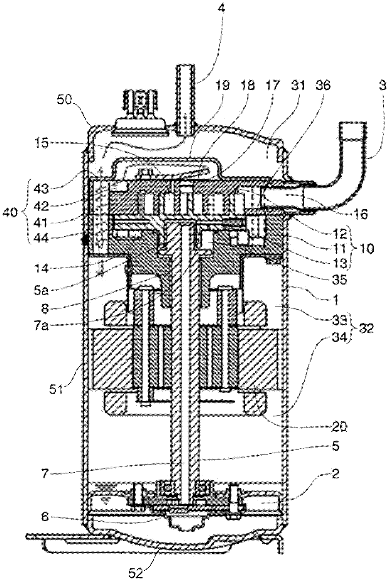
[0055] figure 1 It is a longitudinal sectional view of the compressor according to Embodiment 1 of the present invention. Such as figure 1 As shown, the compressor of this embodiment includes a compression mechanism unit 10 for compressing refrigerant gas and a motor unit 20 for driving the compression mechanism unit 10 in the airtight container 1 . The inside of the airtight container 1 is divided into one container inner space 31 and the other container inner space 32 by the compression mechanism unit 10 . Furthermore, the motor unit 20 is arranged in the other container inner space 32 . In addition, the other container inner space 32 is divided into a compression mechanism side space 33 and an oil storage side space 34 by the motor unit 20 . Furthermore, the oil reservoir 2 is arranged in the oil reservoir side space 34 . In the airtight container 1, the suction pipe 3 and the discharge pipe 4 are fixed by welding. The suction pipe 3 and the discharge pipe 4 communicat...
Embodiment approach 2
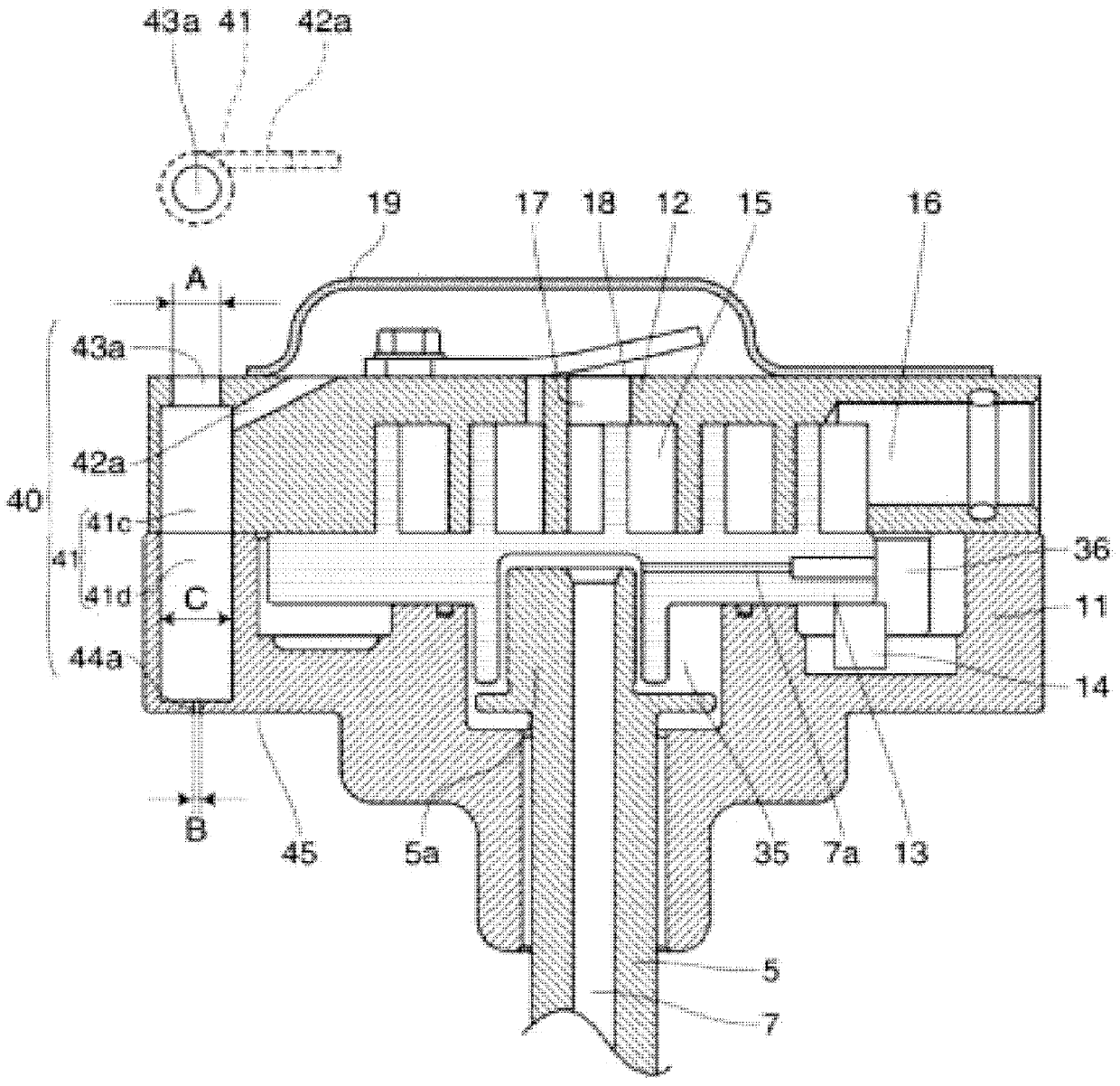
[0073] image 3 It is an enlarged cross-sectional view of a main part of a compression mechanism unit of a compressor according to Embodiment 2 of the present invention. The basic structure of this embodiment and figure 1 The same, so the description is omitted. Additionally, for figure 1 with figure 2 The structures that are the same as those described will be given the same symbols, and part of the description will be omitted.
[0074] In the present embodiment, the outer peripheral portion of the fixed scroll 12 is bored with a stepped portion, whereby the first cylindrical space 41c and the delivery port 43a are formed. The first cylindrical space 41c is formed by processing a non-through hole from the end surface on the side of the fixed surface of the main bearing member 11 (end surface on the side of the overlapping portion). The delivery port 43a, from the end surface on the fixed side of the main bearing member 11 (end surface on the side of the overlapping port...
Embodiment approach 3
[0077] Figure 4 It is an enlarged sectional view of main parts of a compression mechanism unit of a compressor according to Embodiment 3 of the present invention. The basic structure of this embodiment and figure 1 The same, so the description is omitted. Additionally, for figure 1 with figure 2 The structures that are the same as those described will be given the same symbols, and part of the description will be omitted.
[0078] In this embodiment, a cylindrical delivery pipe 46 is provided in the cylindrical space 41 . One end 46 a of the sending pipe 46 forms the sending port 43 , and the other end 46 b of the sending pipe 46 is arranged in the cylindrical space 41 . In addition, in the present embodiment, the other end 46b of the delivery pipe 46 extends into the second cylindrical space 41b.
[0079] An annular space 46c is formed on the outer periphery of the delivery pipe 46, and the inflow portion 42 opens to the annular space 46c. At one end 46a of the deliv...
PUM
 Abstract
Description
Claims
Application Information
 - R&D
- Intellectual Property
- Life Sciences
- Materials
- Tech Scout
- Unparalleled Data Quality
- Higher Quality Content
- 60% Fewer Hallucinations
Browse by: Latest US Patents, China's latest patents, Technical Efficacy Thesaurus, Application Domain, Technology Topic, Popular Technical Reports.
© 2025 PatSnap. All rights reserved.Legal|Privacy policy|Modern Slavery Act Transparency Statement|Sitemap|About US| Contact US: help@patsnap.com