
Portable communication apparatus

A communication device and signal technology, which is applied to devices, electrical components, transmission systems and other directions that make antennas work in different frequency bands at the same time, can solve the problems of large size and area, reduced communication quality, and high antenna correlation coefficient, and achieves increased design flexibility, The effect of improving quality

Active Publication Date: 2013-12-04
TCL CHINA STAR OPTOELECTRONICS TECH CO LTD
View PDF6 Cites 5 Cited by
  • Summary
  • Abstract
  • Description
  • Claims
  • Application Information

AI Technical Summary

Problems solved by technology

[0002] For current communication devices in the prior art, the antenna design method is to arrange different antennas for high and low frequency band signals on the same surface or on the same side to save the occupied surface area of ​​the communication device. When , the correlation coefficients of different antennas for high and low frequency band signals will become quite high, so that the size and area of ​​the antenna circuit design is still quite large. Other design applications of portable communication devices are difficult to realize. In addition, the correlation coefficient of the antenna is high, which will also lead to the reduction of communication quality

Method used


Image

  • Portable communication apparatus
  • Portable communication apparatus
  • Portable communication apparatus

Examples


Embodiment Construction

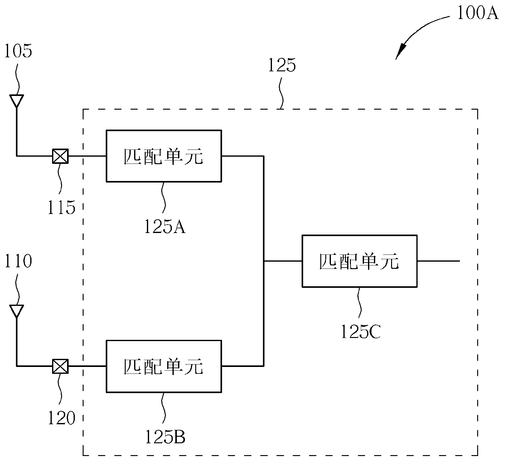
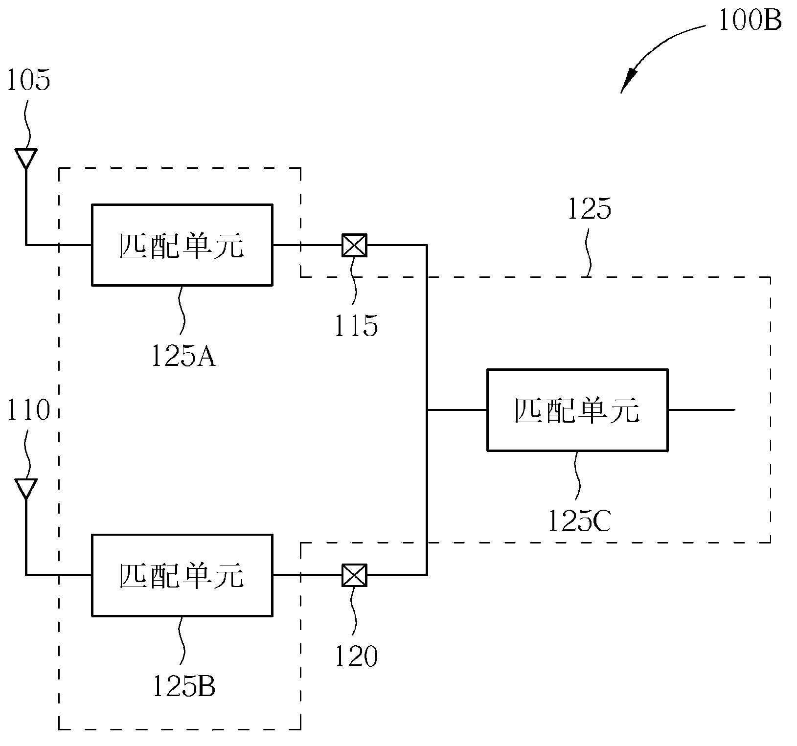
[0027] Please refer to Figure 1A , Figure 1A is a schematic diagram of the portable communication device 100A according to the first embodiment of the present invention. Such as Figure 1A As shown, the portable communication device 100A includes a first antenna radiator 105, a second antenna radiator 110, a first feed point 115, a second feed point 120 and a matching circuit 125, and the first antenna radiator 105 is used for radiation and reception A high frequency band signal, the second antenna radiator 110 is used to radiate and receive a low frequency band signal, the first feed point 115 is coupled to the first antenna radiator 105 and used to receive the signal feed of the first antenna radiator 105 In or out, in other words, the first feed point 115 is used to accept the feed-in and feed-out of the high frequency band signal. When the portable communication device 100A receives the high frequency band signal, the first feed point 115 is used to accept the high freque...


PUM


Abstract

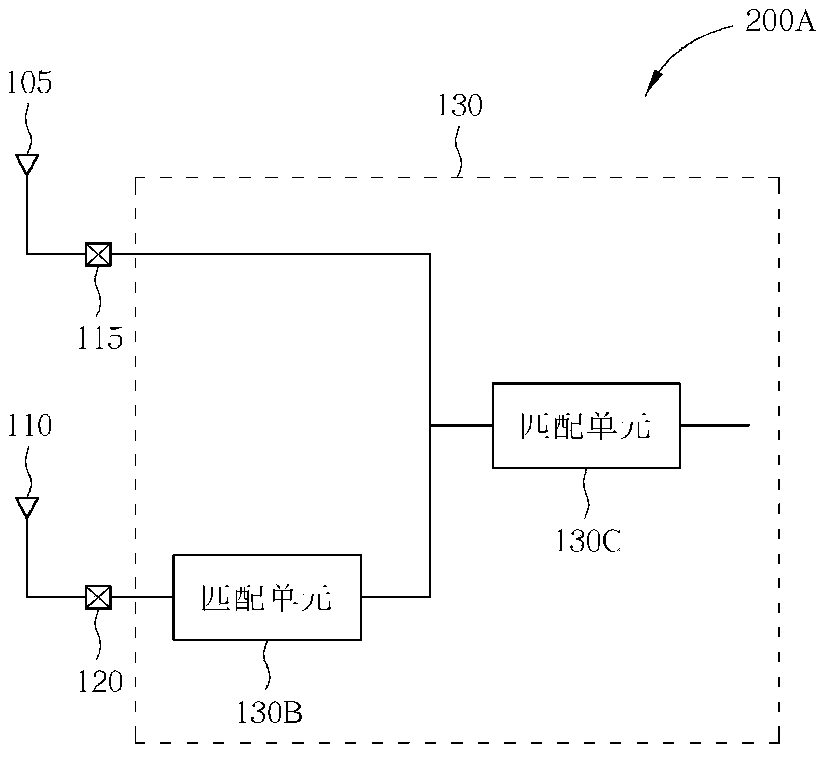
A portable communication apparatus includes a first antenna radiator, a second antenna radiator, a first feeding point, a second feeding point, and a matching circuit. The first antenna radiator is used for radiating a high-frequency band signal. The second antenna radiator is used for radiating a low-frequency band signal. The first feeding point is coupled to the first antenna radiator and is utilized for processing feed-in or feed-out of the signal of first antenna radiator. The second feeding point is coupled to the second antenna radiator and is utilized for processing feed-in or feed-out of the signal of second antenna radiator. The first feeding point is separate from the second feeding point. The matching circuit is coupled to the first and second feeding points, and used for impedance matching with the first antenna radiator and the second antenna radiator.

Description

technical field [0001] The present invention relates to a mechanism of a portable communication device, in particular to a portable communication device designed with a separate antenna. Background technique [0002] For the current communication devices in the prior art, the antenna design method is to arrange different antennas for high and low frequency band signals on the same surface or on the same side to save the occupied surface area of ​​the communication device. When , the correlation coefficient of different antennas for high and low frequency band signals will become quite high, so that the size and area of ​​the antenna circuit design is still quite large. Other designs and applications of portable communication devices are difficult to realize. In addition, the correlation coefficient of the antenna is high, which will also lead to a decrease in communication quality. Contents of the invention [0003] Therefore, an object of the present invention is to disc...

Claims


Application Information

Patent Timeline
Patent Type & Authority Applications(China)
IPC IPC(8): H01Q21/30H01Q23/00H04B1/40H01Q5/10
CPCH01Q23/00H04B1/40H01Q21/30H01Q5/335H04B1/0458H04B1/18
Inventor 谢士炜林卓毅
Owner TCL CHINA STAR OPTOELECTRONICS TECH CO LTD
Learn More