a pay-off machine

A pay-off machine and wire harness technology, which is applied in the manufacture of electrical components, circuits, cables/conductors, etc., can solve the problems of increased maintenance and use costs, accumulation of wire harnesses, and low work efficiency, so as to reduce maintenance and use costs, ensure normal operation, The effect of improving work efficiency

Inactive Publication Date: 2016-05-11
苏州启成精密工业有限公司
View PDF4 Cites 0 Cited by
  • Summary
  • Abstract
  • Description
  • Claims
  • Application Information

AI Technical Summary

Problems solved by technology

[0005] In order to solve the problem that the traditional pay-off machine drives the wire reel to pay off the wire, it cannot guarantee the uniform speed of the wire reel, and it is difficult to directly and effectively detect the tension of the wire harness, and the phenomenon of wire bundle accumulation or jamming often occurs. The work efficiency is low, and it is easy to cause damage to the pay-off machine, which increases the cost of maintenance and use. The invention discloses a pay-off machine to achieve real-time detection of the tension of the wire harness, realize uniform-speed pay-off, and improve work efficiency. The purpose of reducing the damage of the pay-off machine and reducing the cost of maintenance and use

Method used


Image

  • a pay-off machine
  • a pay-off machine
  • a pay-off machine

Examples


Embodiment Construction

[0024] The technical solutions in the embodiments of the present invention will be clearly and completely described below in conjunction with the drawings in the embodiments of the present invention. Apparently, the described embodiments are only some of the embodiments of the present invention, but not all of them. Based on the embodiments of the present invention, all other embodiments obtained by persons of ordinary skill in the art without creative efforts fall within the protection scope of the present invention.

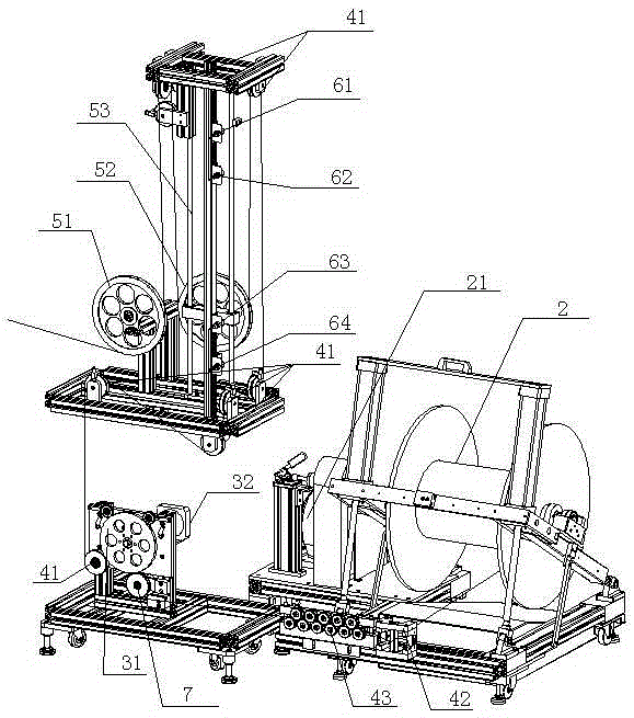
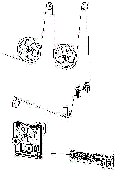
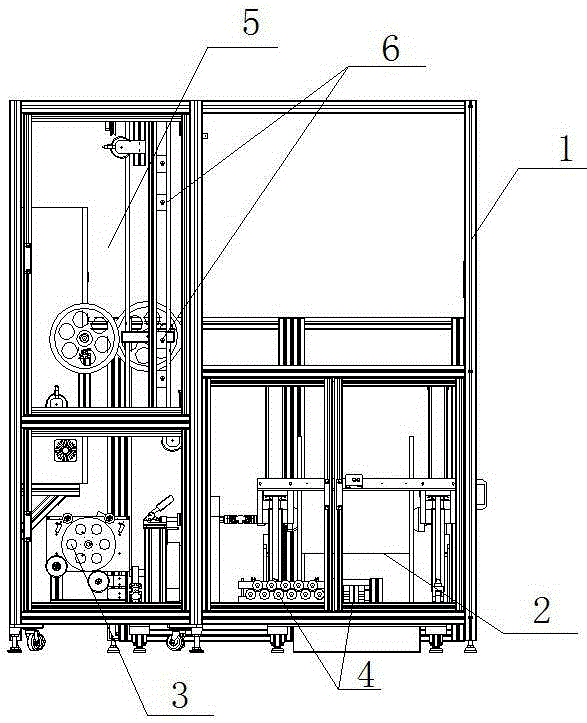
[0025] The invention discloses a wire pay-off machine, which can detect the tension force of the wire harness in real time, realize uniform speed wire release, improve work efficiency, reduce damage to the wire pay-off machine, and reduce maintenance and use costs.

[0026] Such as Figure 1-3 As shown, a pay-off machine includes a frame 1, a wire reel 2 on the frame 1, a traction mechanism 3 for driving the wire reel 2 to pay off, and a guide mechanism 4 for ...


PUM


Abstract

The invention discloses a paying-off machine which comprises a machine frame, a wire coil located on the machine frame, a traction mechanism driving the wire coil to be paid off and a guide mechanism guiding the output of a wiring harness. The traction mechanism comprises a traction wheel and a driving mechanism driving the traction wheel to operate. The paying-off machine further comprises a feedback mechanism used for detecting the tension of the wiring harness and outputting and feeding back a signal. The feedback mechanism comprises a tension sensor arranged at one side of the traction wheel. The tradition mode that the wire coil is driven to be paid off is changed to the mode that paying-off is achieved through the traction of the traction mechanism, the traction wheel is driven to operate through the driving mechanism so that paying-off conducted at an even speed can be achieved. Meanwhile, the tension sensor is arranged, so that the tension of the wiring harness on the portion of the traction wheel is monitored in real time, the signal is fed back in time, the phenomenon that the wiring harnesses are stacked due to over paying-off or the machine is blocked due to insufficient paying-off is avoided, the normal operation of the paying-off machine is guaranteed, the work efficiency is improved, damage to the paying-off machine is reduced, and repair and use cost is reduced.

Description

technical field [0001] The invention relates to a pay-off mechanism, in particular to a flexible pay-off machine. Background technique [0002] The pay-off machine is a kind of auxiliary equipment for wires and cables that is matched with the stranding machine and plays the role of pay-off. [0003] The traditional pay-off machine mainly uses the motor to drive the wire reel to rotate, but because the size of the wire reel is different, and during the continuous pay-off process of the wire reel, as the diameter of the coil gradually becomes smaller, the wire reel rotates once. The length of the released wires is not equal, and the uniform speed of the pay-off machine cannot be guaranteed. Moreover, there is no device for detecting the tension of the wire harness in the pay-off machine, and the tension and relaxation signals of the wire harness cannot be effectively fed back, which often causes Too much wire harness accumulation or too few wire harness jams will affect the c...

Claims


Application Information

Patent Timeline
Patent Type & Authority Patents(China)
IPC IPC(8): H01B13/00H01B13/02
Inventor 谢文雄任振波朱伟博闫琦顾建宏王秀龙
Owner 苏州启成精密工业有限公司
Why Eureka
Try Eureka