Efficient CPU cooling fin

A heat sink and plate-shaped heat sink technology, applied in the direction of instruments, electrical digital data processing, digital data processing parts, etc., can solve problems such as falling off, inconvenient disassembly, melting, etc., to achieve easy replacement, easy disassembly, and meet mutual The effect of sex change requests

Inactive Publication Date: 2013-12-04
KUNSHAN WEIJIN HARDWARE PROD
View PDF6 Cites 0 Cited by
  • Summary
  • Abstract
  • Description
  • Claims
  • Application Information

AI Technical Summary

Problems solved by technology

[0003] The radiating pipes in the prior art are connected to the radiating fins by means of fixed connections such as welding, which is inconvenient to disassemble, and the joints are unstable when heated, which may cause melting and falling off.

Method used


Image

  • Efficient CPU cooling fin

Examples


Embodiment Construction

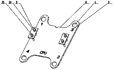
[0014] The present invention will be described in further detail below in conjunction with the accompanying drawings.

[0015] Such as figure 1 As shown, the present invention includes an I-shaped plate-shaped heat sink main body 6, and the heat sink main body 6 is provided with a plurality of vertical through holes 4, and the upper surface of the heat sink main body 6 is provided with at least two rods 12 perpendicular to the upper surface thereof, and the rods 12 is provided with external threads, and the two rods 12 pass through a horizontal plate 8 parallel to the heat sink main body 6, and each rod 12 is connected with a first nut (not shown in the figure) and a second nut 10, the first A nut (not shown in the figure) is located below the horizontal plate 8 , and a second nut 10 is located above the horizontal plate 8 .

[0016] The heat dissipation pipe is arranged between the heat sink main body 6 and the horizontal plate 8, and the height of the horizontal plate 8 is ...


PUM


Abstract

The invention discloses an efficient CPU cooling fin which comprises an I-shaped plate-shaped cooling fin body. A plurality of through holes are perpendicularly formed in the cooling fin body. The efficient CPU cooling fin is characterized in that at least two rods perpendicular to the upper surface of the cooling fin body are arranged on the upper surface of the cooling fin body, outer threads are arranged on each rod, the two rods respectively penetrate through a transverse board parallel to the cooling fin body, each rod is respectively connected with a first nut and a second nut, each first nut is located below the transverse board, and each second nut is located above the transverse board. A cooling tube is arranged between the cooling fin body and the transverse board, the height of the transverse board can be adjusted through adjustment of each second nut so that the heating tube can be clamped tightly. According to the clamping method, detachment is facilitated, when the cooling tube is damaged, the cooling tube is convenient to replace, the requirement for interchangeability is satisfied, and the phenomenon that the connecting strength is influenced by heat in other connecting modes of welding and the like is avoided.

Description

technical field [0001] The invention relates to a cooling device, in particular to a cooling fin used by a computer CPU. Background technique [0002] In recent years, with the continuous increase of the conversion capacity of the power circuit, the power consumption has also increased, and various electronic components have also generated a lot of heat, which has brought about heat dissipation problems, and a heat dissipation device has been produced. The current For CPU components, with the improvement of integration and operating frequency, the requirements for heat sinks will also increase. [0003] The radiating pipes in the prior art are connected to the heat sink by fixed connection methods such as welding, which is inconvenient to disassemble, and the connection is unstable when heated, which may cause melting and falling off. Contents of the invention [0004] The technical problem to be solved by the present invention is to provide a heat sink that is easy ...

Claims


Application Information

Patent Timeline
Patent Type & Authority Applications(China)
IPC IPC(8): G06F1/20
Inventor 朱安邦
Owner KUNSHAN WEIJIN HARDWARE PROD
Why Eureka
Try Eureka