A detection device and detection method based on magnetostrictive guided waves
A magnetostriction and detection method technology, applied in the direction of using sound wave/ultrasonic wave/infrasonic wave to analyze solids, etc., can solve the problems of limited guided wave energy, limited mechanical wave energy, limited detection distance, etc., to improve accuracy and avoid missing defect points , The effect of large guided wave detection distance
- Summary
- Abstract
- Description
- Claims
- Application Information
AI Technical Summary
Problems solved by technology
Method used
Image
Examples
Embodiment 1
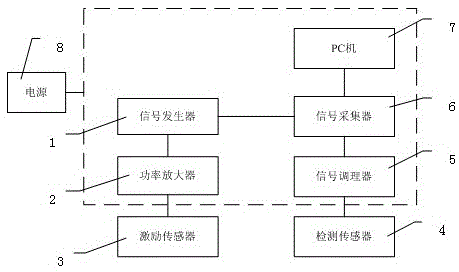
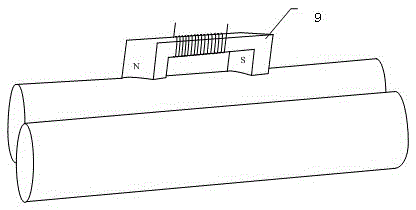
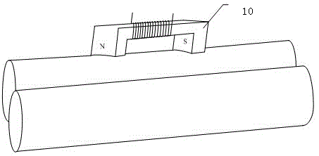
[0038] Example 1, see figure 1 and figure 2, a detection device based on magnetostrictive guided waves, comprising: a signal generator 1, a power amplifier 2 connected to the signal generator 1, an excitation sensor 3 connected to the power amplifier 2, a detection sensor 4, a detection sensor 4 connected signal conditioner 5, a signal collector 6 connected to the signal conditioner 5, a PC 7 connected to the signal collector 6, and a power supply 8 for supplying power to the above-mentioned devices; wherein, the signal generator 1 is also connected to the signal The collector 6; the excitation sensor 3 includes a first permanent magnet 9 arranged axially on the pipeline and an excitation coil wound on the magnetic core of the first permanent magnet 9; the detection sensor 4 includes an axially arranged The second permanent magnet 10 on the pipeline and the detection coil wound on the magnetic core of the second permanent magnet 10 . The detection sensor 4 is 0.7m away from...
Embodiment 2
[0040] Example 2, see Figures 1 to 8 , a detection method based on magnetostrictive guided waves, comprising the steps of:
[0041] S1. The signal generator 1 sends a coded signal to the power amplifier 2. The peak-to-peak voltage is 2V. The power amplifier 2 amplifies the power of the coded signal. The peak-to-peak voltage is 48V, and the peak-to-peak current is 20A, and then sent to Excitation sensor 3, excitation sensor 3 produces elastic wave; Simultaneously, this signal generator 1 sends trigger pulse to the signal acquisition card in the signal acquisition device 6;
[0042] S2, the signal acquisition card stores the collected echo signal in the data memory, then the PC 7 reads the data in the data memory, and stores the read data in the PC 7;
[0043] S3, zero-phase low-pass filtering, that is, the data in the PC 7 is first forward low-pass filtering, then the data is inverted, and then the signal is low-pass filtering to obtain filtered data;
[0044] S4, matched fi...
Embodiment 3
[0047] Embodiment 3 is different from Embodiment 2 in that the duration of a single transmission pulse of the encoded signal in step S1 is 100 US. The time width of the excitation signal is increased, and the energy of the excitation guided wave is increased, which not only increases the effective detection distance, but also improves the lateral resolution of adjacent defects in the radial direction of the pipeline, and improves the signal-to-noise ratio of the echo.
[0048] Preferably, the duration of the single transmission pulse of the encoded signal in the step S1 is 600US. The time width of the excitation signal is increased, and the energy of the excitation guided wave is increased, which not only increases the effective detection distance, but also improves the lateral resolution of adjacent defects in the radial direction of the pipeline, and improves the signal-to-noise ratio of the echo.
[0049] Preferably, the duration of the single transmission pulse of the enco...
PUM
 Abstract
Description
Claims
Application Information
 - Generate Ideas
- Intellectual Property
- Life Sciences
- Materials
- Tech Scout
- Unparalleled Data Quality
- Higher Quality Content
- 60% Fewer Hallucinations
Browse by: Latest US Patents, China's latest patents, Technical Efficacy Thesaurus, Application Domain, Technology Topic, Popular Technical Reports.
© 2025 PatSnap. All rights reserved.Legal|Privacy policy|Modern Slavery Act Transparency Statement|Sitemap|About US| Contact US: help@patsnap.com


