
Energy-saving type positive and negative pressure pneumatic air seal machine

An energy-saving, air-shutoff technology, applied in conveyors, transportation and packaging, conveying bulk materials, etc., can solve the problems of destroying the balance of the wind network, the impeller is easy to get stuck, and the structure is complicated, so as to save the air source and coordinate. Good, ensure the sealing effect

Active Publication Date: 2014-07-16
HUANGSHI LIANGFENG MACHINERY
View PDF6 Cites 0 Cited by
  • Summary
  • Abstract
  • Description
  • Claims
  • Application Information

AI Technical Summary

Problems solved by technology

[0012] The purpose of the present invention is to solve the problem of using impeller air shutoff in pneumatic conveying, ventilation and dust removal system, which has high manufacturing cost, large operating power consumption, easy impeller jamming, and burnt motor, while valve type air shutoff cannot be used in positive pressure pneumatic conveying system. work, and driven by four cylinders, the structure is complex, the action is difficult to coordinate and the balance of the wind network is damaged, and an energy-saving positive and negative pressure pneumatic air lock is provided.

Method used

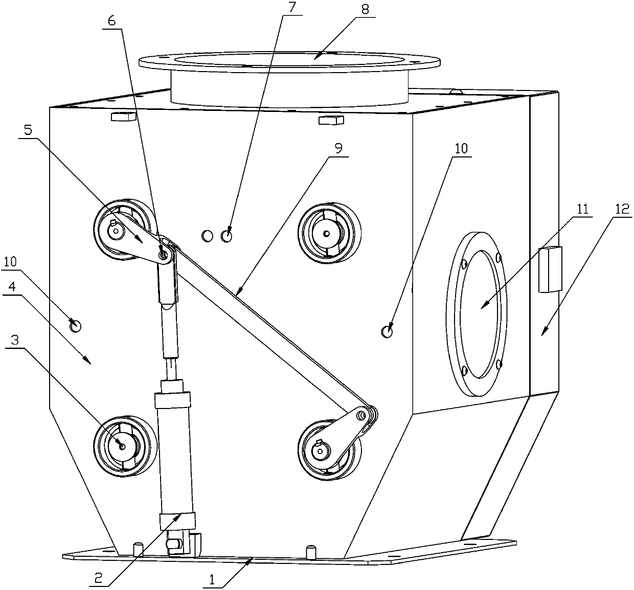
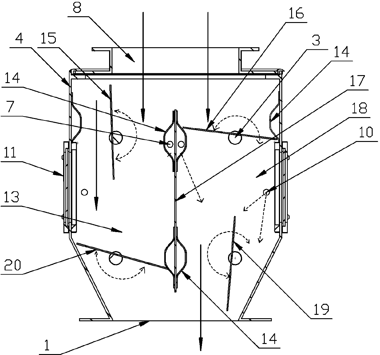
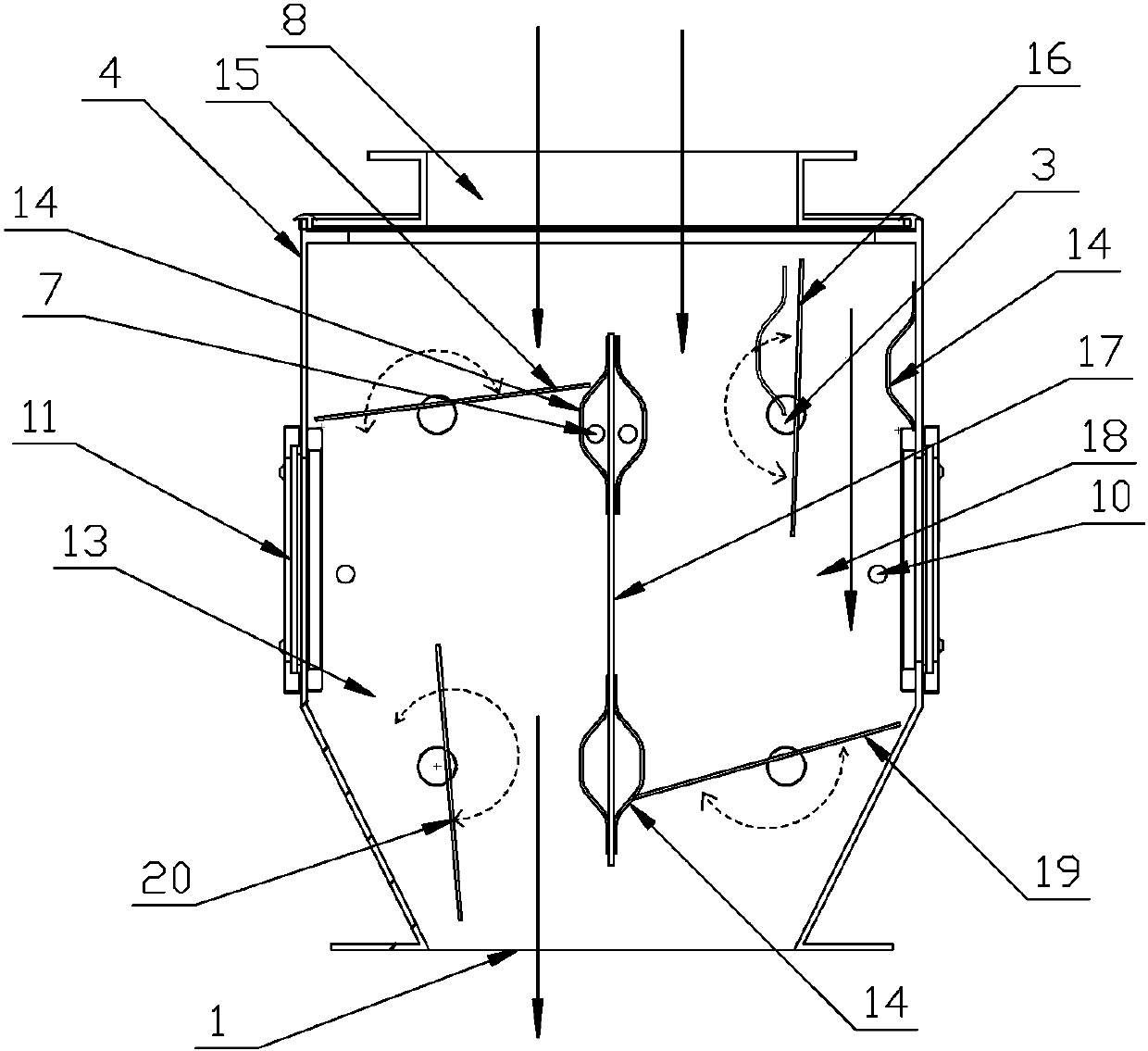

Image

  • Energy-saving type positive and negative pressure pneumatic air seal machine
  • Energy-saving type positive and negative pressure pneumatic air seal machine
  • Energy-saving type positive and negative pressure pneumatic air seal machine

Examples


Embodiment Construction

[0027] see figure 1 , 2 , 3, the present invention comprises housing 4, and the top of housing 4 is provided with feed inlet 8, and the bottom is provided with discharge outlet 1, is provided with the clapboard 17 vertically arranged in the middle part of housing 4 cavity and housing 4 The inner cavity is divided into front and rear two discharge passages 18 and 13, and upper and lower blades 15, 16, 19, 20 are installed in each discharge passage through the upper and lower rotating shafts 3. Sealing plates 14 are provided at the closing positions of the upper and lower blades on both sides, and sealing plates 14 are located at the closing positions of the upper blades on the front and rear side plates of the housing 4. , rear sealing plate 14, arc-shaped design (see figure 2 , image 3), and three jet holes 21 are respectively opened on the two arc-shaped sealing plates 14. , on the housing 4 corresponding to the front and rear air intake passages, there are air inlets 7...


PUM


Abstract

An energy-saving positive and negative pressure pneumatic air lock, which has a housing, the upper part of the housing is provided with a material inlet, the lower part is provided with a material outlet, and a vertically arranged partition is arranged in the middle of the housing cavity to divide the inner cavity of the housing. There are two discharge passages, front and rear, and upper and lower blades are installed in each discharge passage through the upper and lower shafts. A number of air injection holes, front and rear air intake passages are formed between the front and rear arc-shaped sealing plates and the partition, and air inlets are opened on the housing corresponding to the front and rear air intake passages to connect with the air intake pipe; the front discharge The upper shaft in the channel and the lower shaft in the rear discharge channel extend to the outside of the housing, the lower shaft in the front discharge channel and the upper shaft in the rear discharge channel extend to the other side of the housing, A linkage transmission mechanism is installed between the two rotating shafts on both sides of the shell; the invention can not only be applied to positive and negative pressure air transport or dust removal systems, but also solves the problem that the existing valve-type air lock cannot be applied to the positive pressure of the discharge port The problem of the use of the air net system is mainly applicable to the pneumatic conveying and ventilation and dust removal systems in grain, feed, food processing plants, medicine, chemical industry, tobacco, metallurgy, cement and other industries.

Description

technical field [0001] The invention relates to an air closing and unloading device in industrial pneumatic conveying and ventilation and dust removal systems, in particular to an energy-saving positive and negative pressure pneumatic air lock. Background technique [0002] The air shutoff device is an indispensable part in the pneumatic conveying and ventilation and dust removal system. It is a logistics channel for the exchange of solid materials between different air pressure fields such as the wind network and the wind network, and between the wind network and the atmospheric environment. During the material exchange process, the air pressure field or system environment with different pressures is isolated to ensure that the pressure between each pressure field is independent and mutually stable, the air and pressure do not leak, and the gas does not flow through each other. The technical core of the application of this device must first realize the sealing of the inlet ...

Claims


Application Information

Patent Timeline
Patent Type & Authority Patents(China)
IPC IPC(8): B65G53/46
Inventor 程良峰王子奂程骏
Owner HUANGSHI LIANGFENG MACHINERY
Learn More