Novel CPU (central processing unit) cooling fin

A technology for CPU chips and heat sinks, applied in the field of heat sinks, can solve problems such as inconvenient disassembly, melting, and falling off

Inactive Publication Date: 2013-11-27
KUNSHAN WEIJIN HARDWARE PROD
View PDF6 Cites 0 Cited by
  • Summary
  • Abstract
  • Description
  • Claims
  • Application Information

AI Technical Summary

Problems solved by technology

[0003] The radiating pipes in the prior art are connected to the radiating fins by means of fixed connections such as welding, which is inconvenient to disassemble, and the joints are unstable when heated, which may cause melting and falling off.

Method used


Image

  • Novel CPU (central processing unit) cooling fin

Examples


Embodiment Construction

[0014] The present invention will be described in further detail below in conjunction with the accompanying drawings.

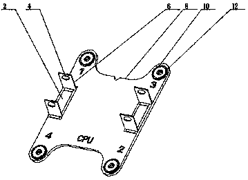
[0015] Such as figure 1 As shown, the present invention includes an I-shaped plate-shaped heat sink body 8, the heat sink body 8 is provided with a plurality of first through holes 12 vertically through, and the upper surface of the heat sink body 8 is also provided with at least one square groove 2 parallel to one side thereof. , the square groove 2 is provided with two sliding pieces 6 facing each other, the sliding pieces 6 can slide horizontally in the square groove 2, thereby adjusting the distance between the two square grooves 2, and the sliding pieces 6 are provided with a second through hole 4 which runs through horizontally .

[0016] Insert the heat pipe between the two slides 6, adjust the distance between the two slides 6 to clamp the heat pipe, then use the bolt to pass through the second through hole 4, and tighten the nut to fix it The heat ...


PUM


Abstract

The invention discloses a novel CPU (central processing unit) cooling fin which comprises a cooling fin body in the shape of an H-shaped plate. A plurality of vertically-communicated first through holes are formed in the cooling fin body. The novel CPU cooling fin is characterized in that at least one square groove parallel to one side of the cooling fin body is formed in the upper surface of the cooling fin body, two sliding pieces are arranged in each square groove face to face and can horizontally slide in the corresponding square groove so as to adjust the distance between the two square grooves, and horizontally-communicated second through holes are formed in the sliding pieces. A cooling pipe is clamped between the two sliding pieces, the distance between the two sliding pieces is adjusted to tightly clamp the cooling pipe, bolts are utilized to penetrate the second through holes and are screw down through nuts, so that the cooling pipe is fixed; due to the clamping mode, the cooling pipes are convenient to demount, and convenient to replace when damaged, interchangeability requirements are met, and connection strength is not affected by heating as compared with that of other connection modes like welding.

Description

technical field [0001] The invention relates to a cooling device, in particular to a cooling fin used by a computer CPU. Background technique [0002] In recent years, with the continuous increase of the conversion capacity of the power circuit, the power consumption has also increased, and various electronic components have also generated a lot of heat, which has brought about heat dissipation problems, and a heat dissipation device has been produced. The current For CPU components, with the improvement of integration and operating frequency, the requirements for heat sinks will also increase. [0003] The radiating pipes in the prior art are connected to the heat sink by fixed connection methods such as welding, which is inconvenient to disassemble, and the connection is unstable when heated, which may cause melting and falling off. Contents of the invention [0004] The technical problem to be solved by the present invention is to provide a heat sink that is easy ...

Claims


Application Information

Patent Timeline
Patent Type & Authority Applications(China)
IPC IPC(8): G06F1/20
Inventor 朱安邦
Owner KUNSHAN WEIJIN HARDWARE PROD
Why Eureka
Try Eureka